Circuit-Zone.com - Electronic Projects
Posted on Monday, May 23, 2011 • Category: Power Supplies
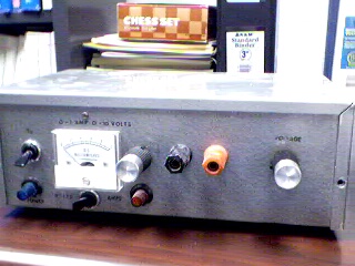
The linear laboratory power supply, shown in the schematic, provides 0-30 volts, at 1 amp current, using a discrete transistor regulator with op-amp feedback to control the output voltage. The supply was constructed in 1975 and has a constant current mode that can be used to recharge batteries. With reference to the schematic, lamp, LP2, is a power-on indicator. The other lamp (lower) lights when the unit reaches its preset current limit. R5, C2, and Q10 (TO-3 case) operate as a capacitor multiplier. The 36 volt zener across C2 limits the maximum supply voltage to the op-amps supply pins. D5, C4, C5, R15, and R16 provide a small amount of negative supply for the op-amps so that the op-amps can operate down to zero volts at the output pins (pins 6). A more modern design might eliminate these 4 components and use a CMOS rail-to-rail op-amp. Current limit is set by R3, D1, R4, R6, Q12, R10, and R13 providing a bias to U2 that partially turns off transistors Q9 and Q11 when the current limit is reached. R4 is a front panel potentiometer that sets the current limit, R22 is a front panel potentiometer that sets the output voltage (0-30 volts), and R11 is an internal trim-pot for calibration. The meter is a 1 milliamp meter with an internal resistance of 40 ohms. Switch S1 determines whether the meter reads 0-30 volts, or 0-1 amp.
Posted on Monday, May 23, 2011 • Category: RC Servo Motors
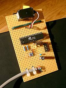 The USB-Servo is a device to control a servo via USB. A servo is a motorized device that is commonly used in remote controlled cars and planes. I built this device to activate a toy puppet. The puppet has a button on its bottom, if you press the button the puppet collapses. When the computer is able to press the button, I can use the puppet to signal information like someone's online-state in the Jabber-network: when my friend goes online, the puppet stands up, when he logs off it collapses.
Servos are connected with three-wire-cables. A red and a black one for the power, and a yellow one for the signal. Power has to be between 4.8 and 6 volts, so the 5 volts from the USB-port is in the range. The signal doesn't take much current, so you can connect it directly to the controller. The angle of the servo is controlled with pulse width modulation (PWM). It gets a signal of about 50Hz (one pulse every 20ms), the length of the pulse tells the servo the angle to adjust.
Posted on Sunday, May 22, 2011 • Category: Motor Controllers
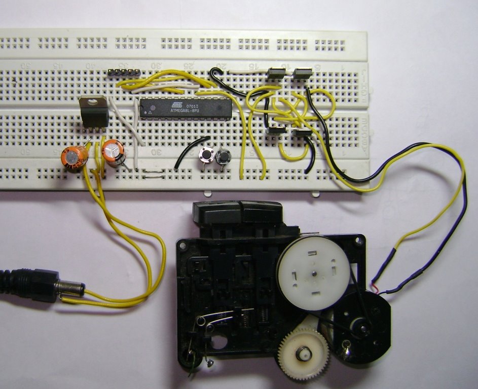 Here is a very simple project of controlling a small DC-motor (taken from an old personal cassette player) with ATmega8. The ATmega8 is having three PWM channels, out of which two are used here. PWM waveforms are fed to MOSFET (RFD3055) H-bridge.
Here, direction is controlled using a two-position toggle switch and speed of the motor is controlled by two push-buttons, one for increasing the speed and other for reducing.
The schematic is geiven here (click on the image to enlarge):
When switch SW1 is closed, OC1A channel is active which will feed the PWM signal to Q1 & Q4 MOSFETs. The OC1B pin will remain low keeping the Q3 & Q2 in OFF condition. When SW1 is toggled to open position, OC1A pin will become low, making Q1 & Q4 OFF and OC1B will feed the PWM signal to Q3 & Q2, resulting in the change in the direction of current flow through motor. Hence, motor rotation direction will change.
The speed is controlled by Push-buttons S2 & S3. Pressing S2 will increase the speed in fixed steps. Similarly, pressing S3 will reduce the speed in fixed steps.
Posted on Sunday, May 22, 2011 • Category: Audio DAC
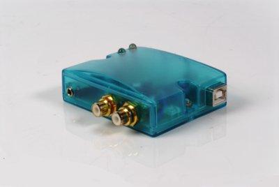 Presented here is high quality USB DAC PCM2906 with built-in headphone amplifier. To see one or more of the same sound card than this is a compact device. That acts as the computer sound card is easy to use. Just plug into a USB port on your computer. It can be used immediately within an IC in PCM 2906 Burr Brown's brand of Neu hear all agree that the sound of course. Used to convert digital signals from the USB port can adjust volume and mute the signal with Noise from the hard drive or CD player can not come to interference. Because a separate circuit from the computer. Add power to drive headphones with a Single Supply OPA2353 Opamp serves as Headphone Amp that does not reconcile the external power supply. This may be an alternative for those who are looking for sound card priced tight, but the quality of glass.
Posted on Sunday, May 22, 2011 • Category: Miscellaneous
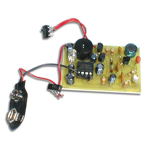 This DIY lightning detector circuit is a very sensitive static electricity detector that can provide an early warning of approaching storms from inter-cloud discharge well before an earth-to-sky return strike takes place. An aerial (antenna) formed of a short length of wire detects storms within a two mile radius.
The circuit emits an audible warning tone from a piezo buzzer, or flashes an LED for each discharge detected, giving you advance warning of impendig storms so that precautions may be observed.
Posted on Saturday, May 21, 2011 • Category: Amplifiers
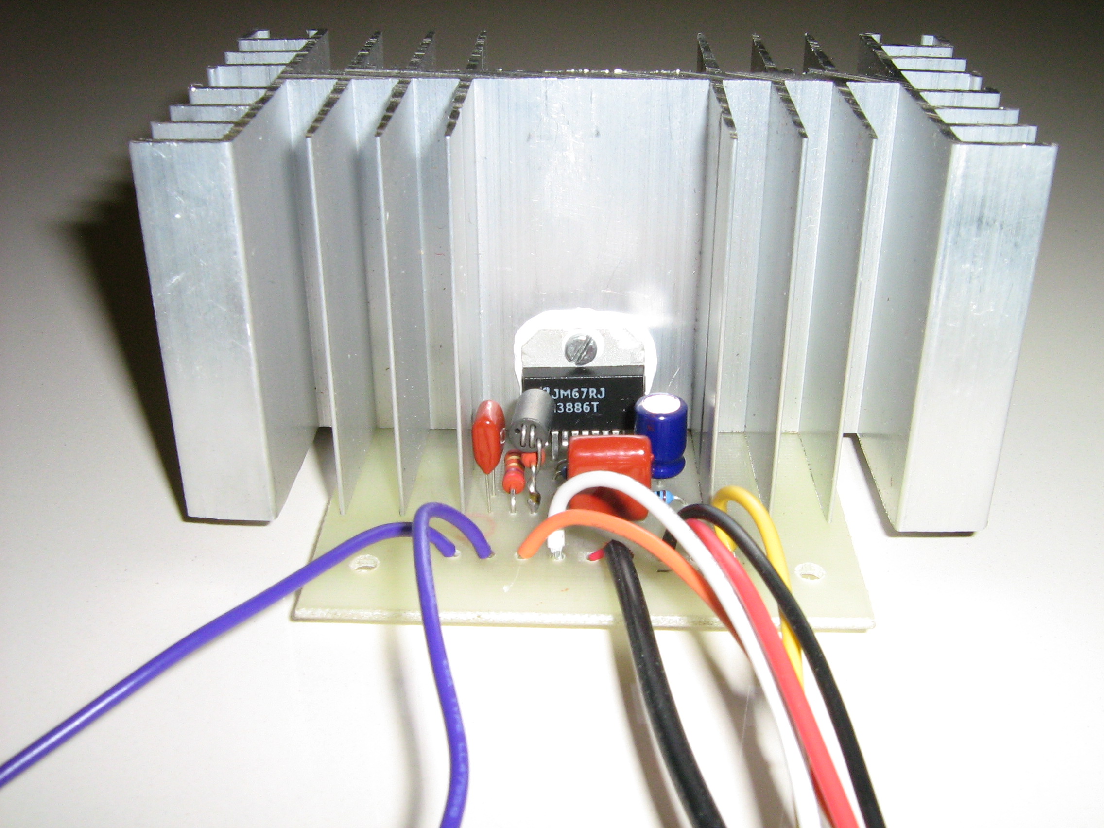 Presented is 68 watts LM3886 Power Amplifier with the use of popular LM3886 amplifier integrated circuit. Amplifier should be fed by source symmetrical good filtered of + 34 and – 34 volts. R2 and L1 is a resistor of 10 ohms / 2watt coiled with 10 to 12 you exhale of enameled thread AWG 20. The circuit integrated lm3886 is a component easy of being found at the electronics stores, for that he is used in several projects of potency audio, some exist circuits with linked lm3886 in bridges for power of up to 150 watts. For most information on the assembly of that circuit, I suggest that sees the datasheet of the lm3886 in the site of the national semiconductors. With the information of the leaf of data you can adapt the circuit with lm3886 your needs.
Posted on Saturday, May 21, 2011 • Category: Oscillators
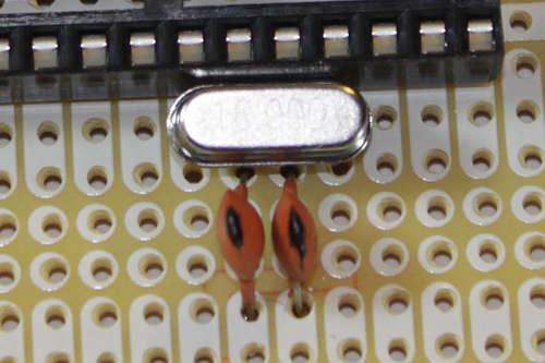 There is a great deal of old amateur gear which many amateurs have decided to restore and bring back to life. While much of the early amateur transceivers work just fine they usually lack a digital readout and must rely on analog dials for tuning. The problem of dial calibration is complicated by the non-linear effects of tuning capacitors. This month's circuit is a 100Khz crystal calibrator using an inexpensive microprocessor crystal and CMOS IC's which are readily available at Radio Shack.
The main problem with building a 100Khz oscillator is the unavailability of 100Khz crystals. Even if you find a vendor willing to cut such a crystal for you, plan on paying $20 or more not including shipping charges. The circuit uses an inexpensive 8MHz microprocessor crystal which can be easily obtained from most parts suppliers. Using a 74HCT393 binary counter IC, we can easily divide down the 8 MHz signal from our crystal into 100Khz or almost any frequency we need.
Posted on Saturday, May 21, 2011 • Category: Antennas
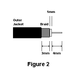 Recently the RASON technical committee was hard at work at the repeater site repairing our 2 meter repeater antenna. One of the members commented to me that I should write an article about collinear arrays so that we could all build our own. While it is not always feasible to home-brew a commercial quality antenna designed to take hurricane force winds, it is very feasible to built a collinear antenna for average use. This article describes a collinear antenna made from very inexpensive RG58/U coaxial cable and encased in PVC pipe.
Before we start building we need to cover some ground about the characteristics of coaxial cable. First remember that there is something called the velocity factor for coaxial cable. For RG58/U coax it is typically .66. This means that when we calculate the length of ½ wavelength in free space we need to adjust its size by multiplying it by the velocity factory. Simply put, RF slows down by the velocity factor when traveling through coaxial cable. All that aside now, lets calculate the ½ wavelength of RG58/U coaxial cable with a frequency of 444 Megahertz.
Posted on Saturday, May 21, 2011 • Category: Power Supplies
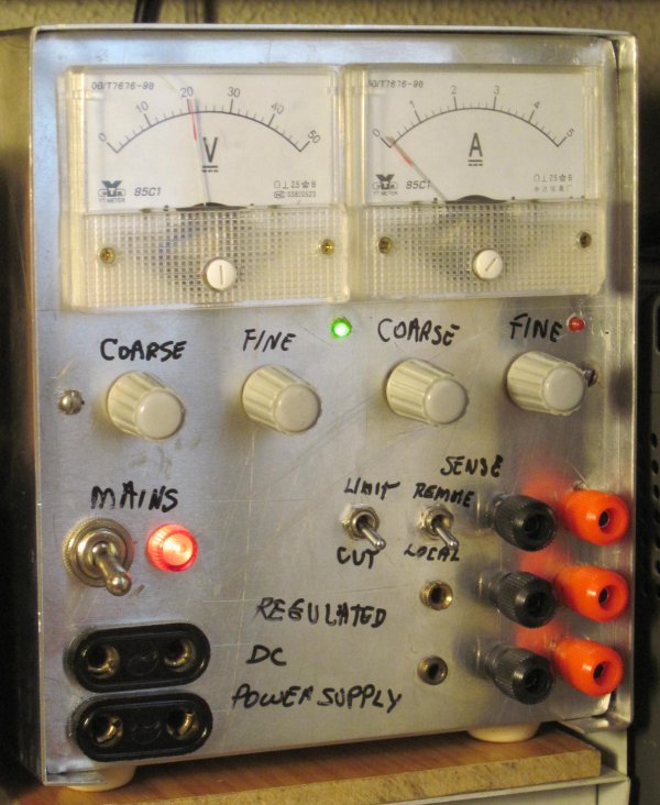 Here's a laboratory power supply with output voltage continuously adjustable from 0 V to 24 V DC, remote voltage sense capability (Sense internal/external), output current limit is continuously adjustable from 0.04 A to 4 A and output current can be limited continuously or output shut down (Limit/cut).
Remote sensing means there are two additional wires which sense the delivered voltage at the load and compensate for any voltage drop along the cables which carry the delivered current. This improves voltage regulation at the load considerably but requires two additional wires for the sensing. A switch allows internal sensing at the output terminals for simpler operation when remote sensing is not required.
I like to have a switch which lets me choose between limiting the output current continuously (useful for charging batteries), or shutting down the output if the current limit is reached (useful for protecting equipment being repaired).
Another thing I like to have in the power supplies I build is a push button switch which multiplies the current scale by a factor of 10. That way one can momentarily press the button and get a much more precise reading of current. By making the switch a push button one cannot forget to turn the function off and risk the instrument being damaged when a large current is put through it. In this case and for now I am not installing this function because I am using the instrument's shunt resistor to sense the current for the electronic control system and I would have to change several things. I might do this in the future.
Posted on Friday, May 20, 2011 • Category: FM Transmitters
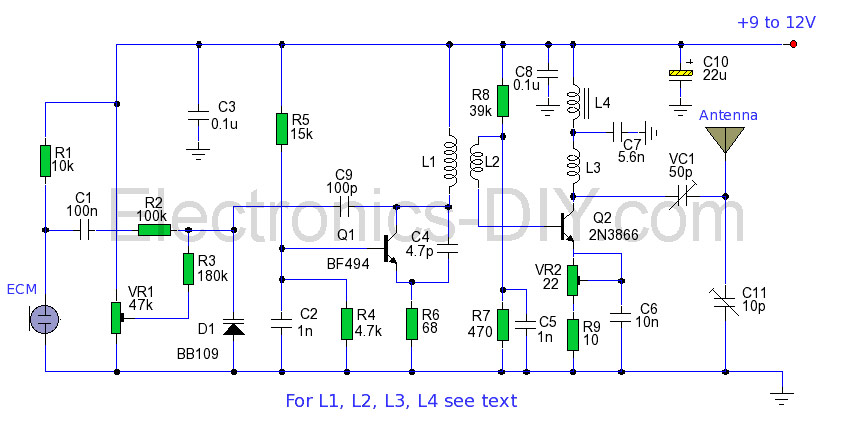 The power output of many transmitter circuits are very low because no power amplifier stages are incorporated. The transmitter circuit described here has an extra RF power amplifier stage, after the oscillator stage, to raise the power output to 200-250 milliwatts. With a good matching 50-ohm ground plane antenna or multi-element Yagi antenna, this transmitter can provide reasonably good signal strength up to a distance of about 2 kilometres. The circuit built around transistor T1 (BF494) is a basic low-power variable-frequency VHF oscillator. A varicap diode circuit is included to change the frequency of the transmitter and to provide frequency modulation by audio signals. The output of the oscillator is about 50 milliwatts. Transistor T2 (2N3866) forms a VHF-class A power amplifier. It boosts the oscillator signal power four to five times. Thus, 200-250 milliwatts of power is generated at the collector of transistor T2.
Circuit-Zone.com © 2007-2026. All Rights Reserved.
|
|
|