Circuit-Zone.com - Electronic Projects
Posted on Friday, March 11, 2011 • Category: Battery Chargers
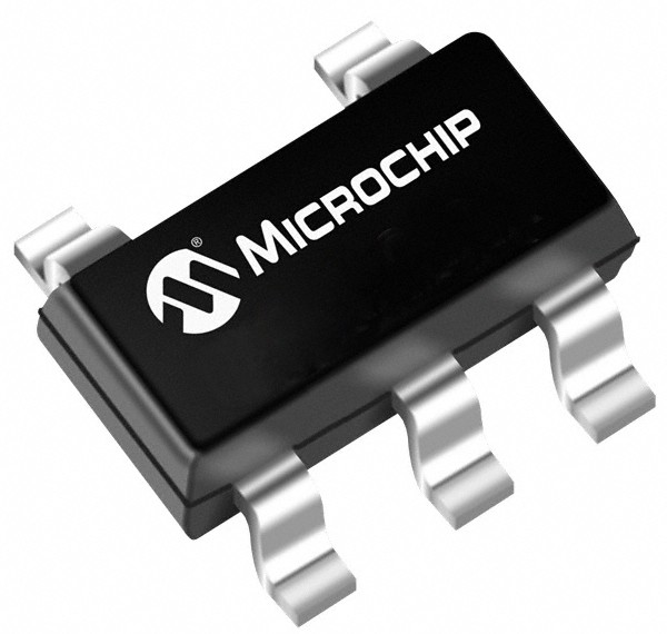
Microchip announced the expansion of its analog power-management family with the MCP73831 battery charger, a fully-integrated, single-cell, Li-ion/Li-Polymer charge-management controller.
Tiny 500mA linear charge management controller can be powered directly from the USB port. Includes integrated pass transistor, current sense and reverse-discharge protection, the MCP73831 charger reduces the number of components needed for battery-charger designs. Its highly accurate, pre-set voltage regulation (maximum accuracy 0.5 per cent to 0.75 per cent) results in more fully charged batteries and extended battery life.
Since the MCP73831 charge-management controller includes a pass transistor, current sense and reverse-discharge protection on a single chip, it reduces the number of system components needed for battery-charger designs, which, added Microchip, lowers overall system costs.
Posted on Friday, March 11, 2011 • Category: Amplifiers
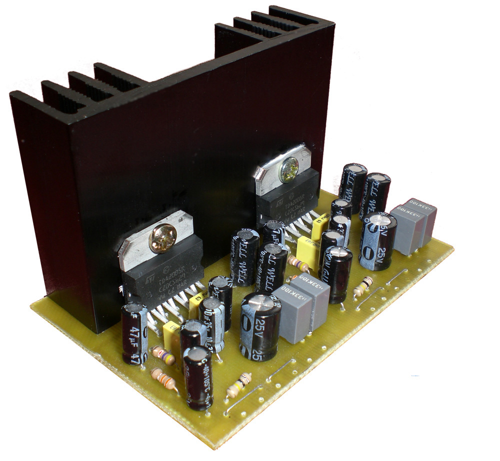 20W TDA2005 stereo amplifier for all suitable applications like amplifying medium power speakers. It is suitable for car use but before, the power supply must be choked with at least 150mH and it must give up to approximately 6 to 7 amps during the upstream performance.
Posted on Tuesday, March 8, 2011 • Category: LED
 This code is for a simple RGB LED controller for 1 RGB LED using a PIC12F675 (or PIC12F629). The pattern is determined by the data in the EEPROM. When the PIC needs a new target for the PWM, it loads it from EEPROM. Pin 4 (GP3) is pulled high because it is used to switch between displays. Please see the source code for more information; the structure and design is commented. The operation of the controller is very simple and so is the wiring.
Posted on Monday, March 7, 2011 • Category: Amplifiers
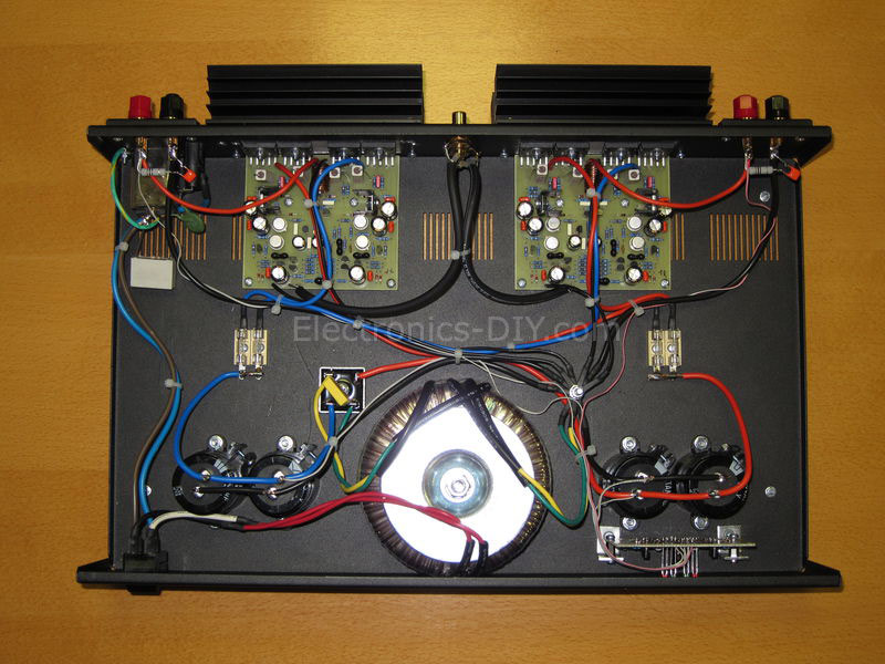 Article about building Marshall 200W Leach Amplifier. For many years I looked for construction of HiFi amplifier wit a good parameters, enough power reserve and simple construction. I built a couple of amplifiers with integrated circuits MBA810, TDA2005, LM3886, but I was disappointed by their output quality and noise. I decide to built a classic construction with discrete components and bipolar transistors. Construction from Mr. Dudek was interesting, but I didn't like used components and complexity. All of my requirements satisfied construction of the Leach Amp. Circuit author publicates in a February 1976 in american journal. From these days circuit was not practically changed. Little changes are descripted on authors page.
Posted on Saturday, March 5, 2011 • Category: LED
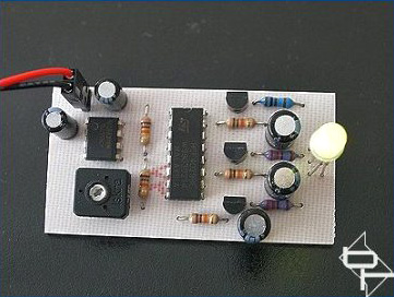 The implementation of a RGB LED fader using 555 timer and 4029 digital IC is the objective of this project.
During the operation, the RGB LED is continuously cycled through the colors of the rainbow where the speed at which the colors change is adjustable. The switch between the different colors makes the effect very noticeable while a more relaxed effect happens when the colors fade into each other. These two options can be selected on this device.
The pulse generator based form a standard 555 timer is formed by IC1, C1, R4, R5, and VR1. The frequency of which, and hence the speed of the effect, as adjusted using the pre-set VR1. The pulses are fed into IC2 which is a 4029 binary counter whose outputs continuously count in a binary progression between 1 to 7. The transistors Q1, Q2, and Q3 are being driven by these outputs which in turn control each of the three colors of the RGB LED.
By passing through an RC network, the pulses are shaped before they reach their respective transistors. The fading effect between the colors or abrupt changing is produced by this shaping.
Posted on Friday, March 4, 2011 • Category: FM Transmitters
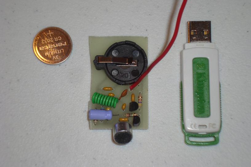 The goal of this project is for me personally to learn a little more about fm transmitters and fm bug making (may the HAM radio gods bless me in this pursuit). The ideal outcome of this project is a very small and full functional FM transmitter that we can stick into a plastic mint box.
In order to be able to build this, we'll have to learn a lot about amplifiers, LC oscillators, mixers, antennas and FM. This project assumes you're already comfortable build your own PCB boards. If you're not please take a look at the homemade pcb's tutorial before you continue. It will help you out a lot.
Posted on Friday, February 25, 2011 • Category: Amplifiers
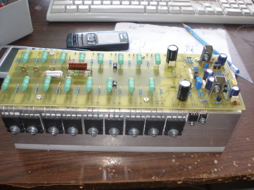 Here's a Leach Amplifier based on 2SC5200 and 2SA1943 output power transistors that can provide up to 700W of power. The mechanical design is relatively simple, the transistors are placed on the two cooling profiles with a height of 66 mm, width 44mm, overall length 260mm. They are turned against each other Thus, from the cooling tunnel. Coolers are attaching the nylon backing which allows the assembly of transistors without washers, and thus better transfer of heat. DPS amplifier is at the top of the tunnel and the transistors are soldered from the bottom of PCB.
Posted on Friday, February 18, 2011 • Category: Amplifiers
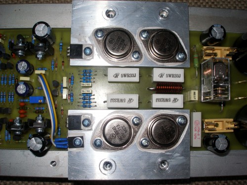 The amplifier design includes not only the final stage of the source (rectifier, filter) and protection against DC voltage output amplifier and speaker connections delayed.
As already mentioned, the amplifier is designed as a single-module. This means that on one common board rectifier, filter capacitors, protection And definitely amplifier.
Regarding the components of the external solution, the solution based on the original Mr. Marshall Leach. The proposal is adapted for the proposal. in the amplifier are used for temperature sensing diodes are replaced with one sensing transistor mounted on the end of the main condenser and field Tranda. This transistor provides a thermal feedback and thus of a stable quiescent current amplifiers.
Privacy speakers are powered directly from the voltage amplifier. As for mechanical design, is probably the most complicated in the whole amplifier. Cooling is done by the Al blocks that are attached to the main cooling profile. ZH6465 profile is used. The terminal transistors to heat is released through Al strips with a thickness of 6 mm in the lateral beams and passing into the cooler. more pictures.
Posted on Friday, February 18, 2011 • Category: PIC
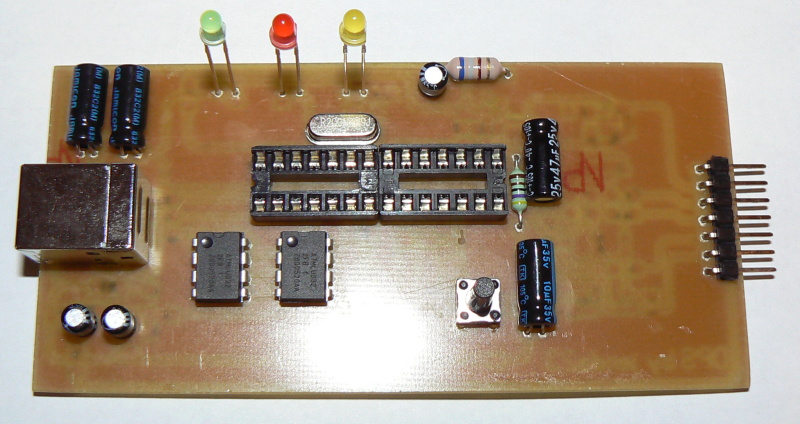 For a long time I needed a good programmer pussy, even if it is programming, so from time to time the application gets where it is used. So I decided to build the programmer. I chose between a couple of projects from different authors, but eventually won PICkit2. Microchip released the schema directly in the user manual for the programmer. On the Internet there are multiple versions of the programmer, it's usually cropped version of the log analyzer features, UART terminal, etc., 12V inverter is a modified version of it and control the MOSFETs, unlike bipolar transistors used in the original design. And it also showed that becomes due to the switching inductance feta leave. Finally, I chose to use the original scheme, although it is quite complicated and the parts used in our country can not normally buy, but my problems with finding parts easily solved. I bought a transistor, the 16F2550 PIC and a few other things, resistors and fry the rest I bought from "us". The price is pretty high, unfortunately, moving it around and 600CZK, the main prize and two processor makes the EEPROM. Below we describe the involvement and put into operation.
Posted on Tuesday, February 15, 2011 • Category: Amplifiers
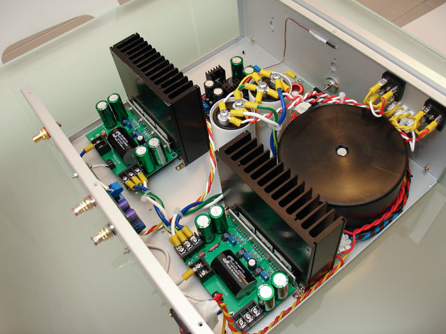 After I built several LM3875 and LM3886 gainclone amplifiers, I was totally impressed by their audiophile sound quality. My design goal is to create a audio power amplifier that can deliver 300W into my 4-ohm DIY speaker with low distortion. I want it to produce deep, tight and punchy bass while keeping the excellent mids and highs from my other gainclones. My design uses a PCB to hold 3 paralleled 3886s (i.e. PA150), and then I use the DRV134 to bridge 2 of the PA150 PCB boards. The function of DRV134 is to convert the un-balanced input signal to a balanced signal, so that the non-inverted signal is fed to one PA150, and the inverted signal is fed the another PA150. One of the PA150 is connected to the speaker's positive input, and the other PA150 is connected to the speaker's negative input. Because of this push-pull configuration, the total gain of the amplifier is doubled. Each PA150 has a gain of 20, so the gain of the BPA300 is 40.
Circuit-Zone.com © 2007-2026. All Rights Reserved.
|