Circuit-Zone.com - Electronic Projects
Posted on Monday, March 21, 2011 • Category: Remote Control
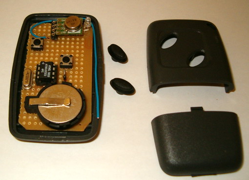
There are lot of remote controls like infrared, RF, SMS (like my other circuit) and more. The basic small-range remote controls are 2, Infrared and RF (Radio Frequency). One of the weaks of Infrared is that the signal can not pass the walls. So, if you want to control your garage door, the only way is to use some RF remote control. The circuit (transmitter and receiver) use few components and ordinary (I love few component circuits) . Its easy to build it because you don't have to tune-up any coil or variable capacitor. The RF modules are fix to work in 418MHz area.
Posted on Monday, March 21, 2011 • Category: LED
 In this page we will introduce a great project designed by Toon Beerten. This project can become a very interesting add-on for your room that's absolutely sure it will impress everyone. As you can see on the photos, we talk about a color fading lamp, that looks amazing!
The purpose of this page is to try to give some hints building it successful. This high power led mood light is based on PIC16F628 and the ability of this mcu to produce PWM pulses. Varying pulse width we can produce millions of color combinations using only the three basic colors. So only one RGB (Red-Green-Blue) led is capable producing a rainbow of fading colors.
With the help of four switches we can handle all functions of the lamp. We can choose fading or jumping between colors, we can select a rainbow style or a random color changing behavior, we can choose slow or fast changing of colors and we can pause on a desired color.
Finally we will make some power dissipation measurements to help us select an appropriate power supply unit.
Posted on Monday, March 21, 2011 • Category: LED
 There is a major advantage to using LEDs for lighting: various dimming techniques allow seamless control of the light output from the LED source. While LEDs are efficient light sources, the dimming feature also allows for considerable power savings. Control over the light output also helps to set the desired ambience.
PWM dimming is preferred to analog dimming for several reasons. For many applications PWM dimming maintains the color of the light output regardless of the dim level. For circuit design, PWM control is more immune to noise; the control signal need not be accurate in both voltage levels and dimming frequency; and the driver circuit design is less complex. PWM dimming usually requires a control line that carries the PWM dimming signal, in addition to the two power-supply lines. This standard configuration is, however, a drawback for applications that use common dimming for a large number of lights; the configuration also makes it difficult to replace the incandescent light installations with two-wire supply lines that depend on supply chopping for dimming control.
Traditional, crude LED driver circuits that work with power-supply dimming are problematic. Those drivers turn off power to the LEDs gradually as the input filter capacitors discharge to the minimum operating voltage of the driver. That process can cause the input and output filter capacitors to discharge to low levels. Then when the supply is turned back on, a huge surge of current flows to replenish the capacitor charge, thus causing EMI issues and premature dimmer damage. To prevent these various issues, those circuits use large inductor filters that increase cost.
The LED driver reference design described here addresses this basic design challenge with PWM dimming. This LED driver implements PWM dimming based on supply chopping; it does not cause any supply current overshoot. The design provides up to 90% efficiency while operating from a 24V supply. It allows a unidirectional supply input with an efficient semi-MOSFET bridge rectifier at the input. Figure 1 shows the top view of the design board.
Posted on Monday, March 21, 2011 • Category: Miscellaneous
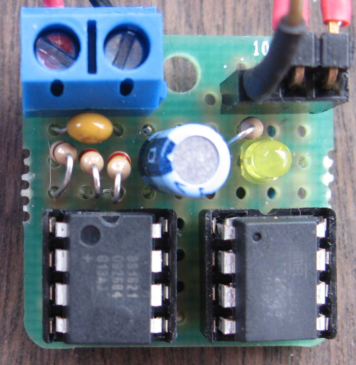 I became interested in the ATtiny85 processor recently. Up till now, my projects were based on the ATmega328 or the ATmega644. The ATtiny85 is just that, tiny - only 8 pins vs. 28 on the ATmega328. The photo on the left shows the new X10 temperature transmitter, with the DS1621 temperature chip on the left and the ATtiny85 on the right.
Posted on Friday, March 18, 2011 • Category: FM Transmitters
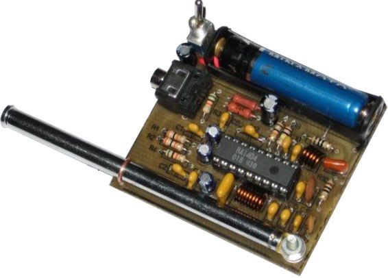 Circuit of stereo FM transmitter of of high quality using integrated circuit ba1404 for mp3, mp4, ipod, computer, radio of the car. Transmit of your equipment of portable audio for the radio of your car, transmitters of fm of low potency are the ideal for transmission wireless of audio sign for fm receivers. Mainly in that case that is treated of transmitter of FM stereo with ba1404.
The heart of that circuit is the circuit integrated ba1404, that is a mini fm transmitter, that already counts with the necessary internal circuits for transmission in fm. just being necessary to increase some components discman or any other audio source turning the wireless. If you already set up other transmitters of transistorized fm it will see that when setting up that with having integrated BA1404, that the quality of the sound and the frequency stability is excellent. Besides the but it presents easy assembly.
Posted on Wednesday, March 16, 2011 • Category: Amplifiers
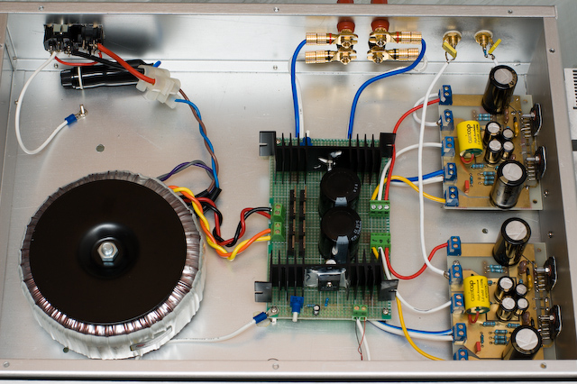 This amplifier is based on the PA100 parallel amplifier detailed in National Semiconductor's application note - AN1192.
Since my DIY speaker is 4-ohm and somewhat difficult to drive, I want to have a more powerful amplifier to match with it. Therefore I designed this amplifier which uses two LM3886 per channel, in parallel circuit. This amp can deliver about 50W into a 8-ohm speaker and 100W into a 4-ohm speaker. This is a stereo amplifier and therefore 4 LM3886s are used. The LM3886 circuit is in a non-inverted configuration, so the input impedance is determined by the input resistor R1, i.e. 47k. The 680 ohm and 470pF resistor capacitor filter network is used to filter out the high frequency noise at the RCA input. The 220pF C4 and C8 capacitors are used to shot out the high frequency noise at the LM3886 input pins.
I used high quality audio grade capacitors at several locations: 1uF Auricap at the input for DC blocking, 100uF Blackgate for C2 and C6, and 1000uF Blackgate at the supply filter.
Posted on Wednesday, March 16, 2011 • Category: Amplifiers
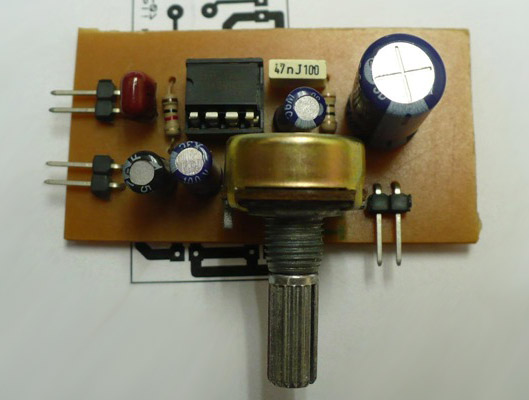 This amplifier is very easy to make and very compact, works with a single power source whose value can be between 4V and 12V.It is based on the use of a type LM386 amplifier, capable alone to issue a power of several hundreds of milliwatts to a load (HP) of 8 ohms, while consuming only a few mA at rest. Ideal for make a small portable battery powered amp. The LM386 is a power amplifier designed for use in low voltage consumer applications. The gain is internally set to 20 to keep external part count low, but the addition of an external resistor and capacitor between pins 1 and 8 will increase the gain to any value from 20 to 200.The inputs are ground referenced while the output automatically biases to one-half the supply voltage. The quiescent power drain is only 24 milliwatts when operating from a 6 volt supply, making the LM386 ideal for battery operation.
Posted on Tuesday, March 15, 2011 • Category: Miscellaneous
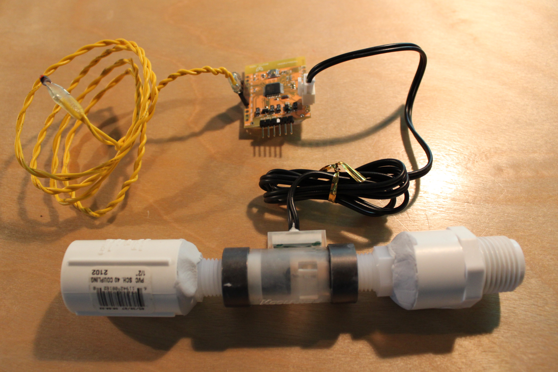 Working with the interaction design team, a bunch of us at Teague have been tinkering with measuring water, analyzing usage data in realtime to affect behaviors, and storing it to see patterns over time.
At the heart of the exploration was a need to cheaply measure water from the tap. Water meters vary quite drastically in price (from $250+ for industrial grade sensors to $6 for garden hose attachments that limit total usage based on rough estimates). We settled on a $20 water meter used for PC cooling systems (the INS-FM17N by Koolance) due to its accuracy, low price, small size, and electronic sensing method that could be easily measured by a microcontroller (such as an Arduino).
Posted on Tuesday, March 15, 2011 • Category: Miscellaneous
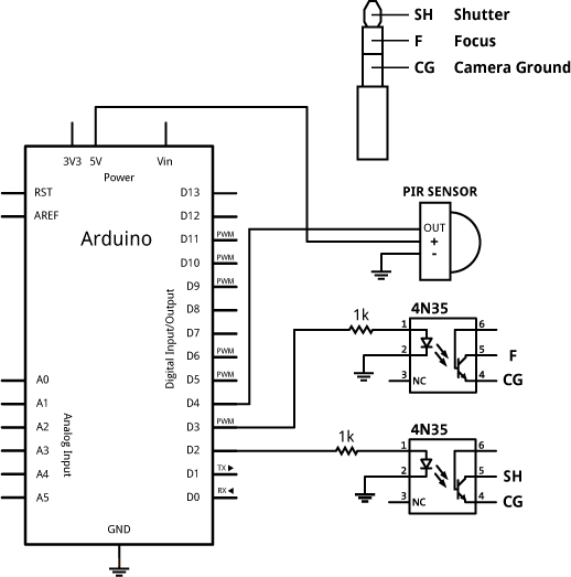 I made a relatively simple attachment to my Canon SLR to create a motion activated camera using Arduino. A lot of this was based on and inspired by the intervalometer project at The Honey Jar. I made some changes to his circuit to use a 4N35 optocoupler instead of reed relays.
Posted on Tuesday, March 15, 2011 • Category: Miscellaneous
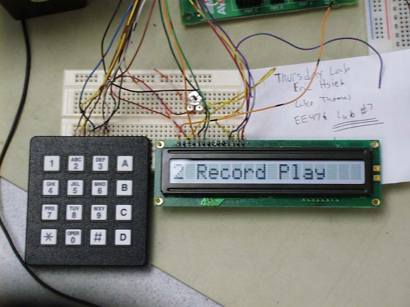 Every group wants their final project to be something that will be remembered long after they're gone. Some do highly sophisticated and complex projects that entail upwards of a hundred hours to complete. Yet others go out of their way to develop something 'cool' and 'fun'. Luke and I decided that we wanted to be in this second category, because developing something that's 'cool' would also be fun to do. So in deciding what to design we tried to think of something that would catch the attention of the people in the lab. The easiest way of doing this is to create something that would make noise or play music so everyone in the lab could enjoy it. Realizing this would be the best way to go, we decided to create a synthesizer that could record and playback notes, 'teach' the user how to play a simple melody, and also play some prerecorded tunes. After all, don't you think being remembered as the group that played back the Imperial March theme from Star Wars is cooler than a paper tape reader? (no offense to those groups doing paper tape readers)
Circuit-Zone.com © 2007-2026. All Rights Reserved.
|
|
|