Circuit-Zone.com - Electronic Projects
Posted on Wednesday, January 12, 2011 • Category: Test and Measurement
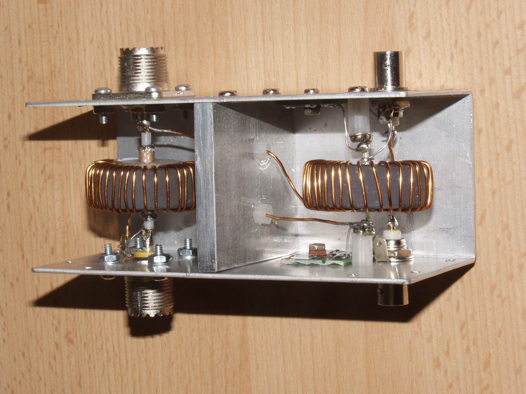
A pair of AD8307 RSSI (Received Signal Strength Indicator) chips are used to produce DC voltages that are proportional to the logarithm of the Forward and Reflected power levels. These DC voltages can then be subtracted in an Op Amp to produce a voltage proportional to SWR which is essentially independent of power level. The Forward DC voltage also drives a separate Power meter. I have modified Paul's design to use a "Stockton" directional coupler, and to provide a peak-reading capability. The meter automatically provides an accurate readout of SWR for any power level between 10mW and 1000W. I arranged for the Power meter to cover the range 100mW to 1000W, but it is easy to change the circuit to set upper and lower power limits to any values in the range 100uW to 1000W.
Posted on Monday, January 10, 2011 • Category: Test and Measurement
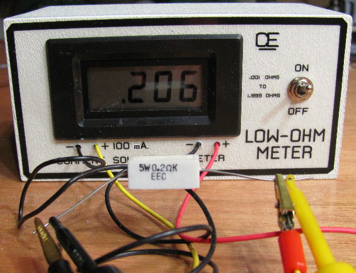 A very simple circuit to measure low resistance values from 0.001 up to 1.999 Ohm. With a "Direct Resistance Readout in Ohms". You must use two separate batteries. One for the DMM and one to supply power to the LM317LZ. I recommend the LM317LZ, which is the 100 mA, T0-92 version of the normal LM317. But you can also use the LM317, in the T0-220 package, if you want. The trimpot must be set precisely to deliver 100.0 mA out to get truly accurate resistance measurements.
So you need a very accurate Milli-Amp Meter to adjust this Correctly.
(And like Any Test Equipment, This Calibration should be Re-Checked once a year or so.)
Posted on Monday, January 10, 2011 • Category: Test and Measurement
 The project came from an Italian magazine Nuova Elettronica N212. It's very simple but interesting ESR Meter. I've built it and tested some capacitors and it's very useful.
It measures the ESR (Equivalent Series Resistance) of capacitor (electrolytic and not) that s used to tell if a capacitor is good or not. ESR Meter uses a bridge circuit that works at 100KHz.
Posted on Sunday, January 9, 2011 • Category: Test and Measurement
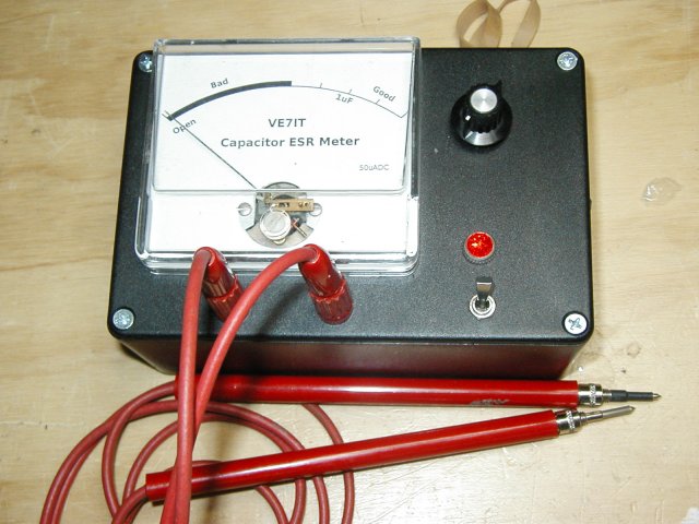 A typical capacitor checker measures the capacity (usually in micro farads) of the test capacitor. Some advanced units also test for leakage current. Most of these testers require that the capacitor be removed from the circuit. Unless the capacitor has totally failed, they will not detect a high ESR value. In a typical circuit, there may be 10's or 100's of capacitors. Having to remove each one for testing is very tedious and there is a great risk of damaging circuit boards. This tester uses a low voltage ( 250mv ) high frequency (150khz) A/C current to read the ESR of a capacitor in the circuit. The in circuit testing is possible because of the low voltage used for obtaining the measurement. The voltage is low enough that solid state devices in the surrounding circuitry are not activated and do not affect the low resistance reading we are attempting to obtain. A lot of capacitor checkers will be damaged if you happen to test a charged capacitor. This circuit is A/C coupled and will withstand up to 400vdc of charge on a capacitor (but watch your fingers!). The ESR checker will not detect shorted capacitors as they will read with a very low ESR value. If you are trouble shooting a circuit, you will have to use several instruments including your nose, voltmeter and oscilloscope to locate all the possible failure modes. My experience has found that the ESR meter catches about 95% of capacitor problems and potential problems.
Posted on Sunday, January 9, 2011 • Category: Test and Measurement
 When teamed up with an oscilloscope, this simple circuit provides a means of measuring capacitor ESR.
A 555 timer (IC1) configured as a 2.3kHz free-running oscillator acts as the timebase. It provides narrow (7.7µs) pulses to the capacitor under test via a NAND Schmitt trigger (IC2) and transistor Q1.
A 100Ω resistor in series with Q1 limits current flow to about 50mA. Therefore, an ESR of 1Ω will produce pulses across the test capacitor of 50mV, which means that an oscilloscope with a vertical sensitivity of 5mV can measure ESR down to 0.1Ω or less.
Posted on Friday, January 7, 2011 • Category: PIC
 USB Input / Output Board is a spectacular little development board / parallel port replacement featuring PIC18F2455 / PIC18F2550 microcontroller. USB IO Board is compatibile with Windows / Mac OSX / Linux computers. When attached to Windows IO board will show up as RS232 COM port. You can control 16 individual microcontroller I/O pins by sending simple serial commands. USB Input / Output Board is self-powered by USB port and can provide up to 500mA for electronic projects.
Posted on Monday, January 3, 2011 • Category: Test and Measurement
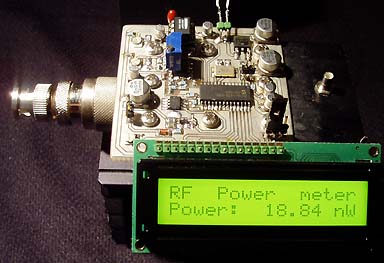 This project will explain how I build my new wattmeter.
This watt meter will be able to measure power from 300nW to 30W @ (0-500MHz).
This wattmeter is based up on a dummy load of 50 ohm which can handle 50W.
The measurement will be displayed in Watt on a 2x16 Char display.
Posted on Monday, January 3, 2011 • Category: Test and Measurement
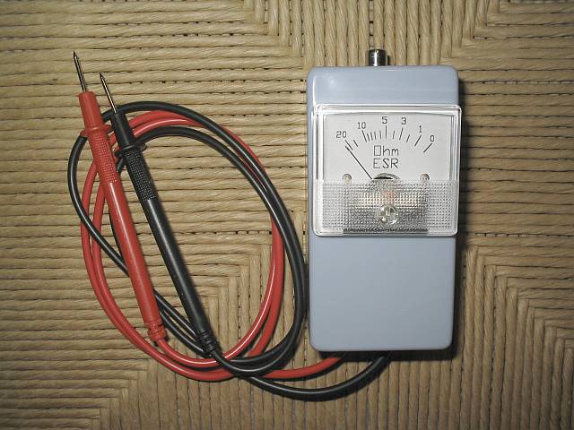 Electrolytic capacitors are by far the electronic parts that suffer aging soonest. If you have any electronic equipment that over the years has degraded its performance, developed quirks, sometimes ending in complete failure, the chances are good that one or more electrolytic capacitors inside it have degraded, causing the problem. Electrolytic capacitors age in several ways: They can become electrically leaky, causing a DC current through them that can make them blow up. They can shift in capacitance value. But the most common way they degrade, by far, is by unduly increasing their equivalent series resistance, which is the undesired internal resistance that appears in series with the wanted capacitance at a given frequency.
Posted on Wednesday, December 29, 2010 • Category: FM Transmitters
This small FM transmitter with a range of about 50 meters designed for connection to the USB port. With lots of mini-transmitters then you have a comprehensive, action-packed radio program. Due to the power supply via the USB port of a high frequency stability is achieved. Alternatively, the receiver, a battery 5 to 12 volts to operate.
Posted on Wednesday, December 29, 2010 • Category: FM Transmitters
Easy to build high-quality PLL FM transmitter with typical output power of 5 W and no-tune design. The transmitter includes RDS/SCA input and Audio/MPX input with optional pre-emphasis. It can be used with or without stereo encoder. Tuning over the FM band is provided by two buttons that control dual-speed PLL. The transmitter can work also without the LCD display. Some experience with building devices of this kind are highly recommended.
Circuit-Zone.com © 2007-2026. All Rights Reserved.
|
|
|