Circuit-Zone.com - Electronic Projects
Posted on Monday, June 20, 2011 • Category: TV Transmitters
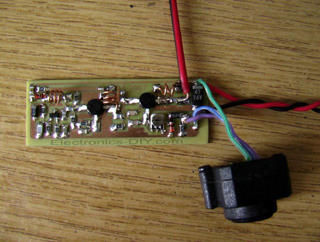
This is a TV transmitter for transmitting video of various video sources such as video cameras, Satellite receivers, DVD players, game consoles, etc. TV transmitter's circuit is working on the 470-580 MHz frequency and can be received on UHF channels 21-34. TV Video transmitter can radiate as far as 300 meters by using a 10-20 cm wire antenna. TV transmitter requires voltage of 9-15 Volts. However, you can also use a 9v batteries. Oscillator is based around BF199 and BFR90 RF transistors. If needed the range of TV transmitter can be extended by replacing BFR90 with 2N3886 transistors.
Posted on Saturday, June 18, 2011 • Category: PIC
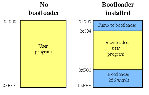 A bootloader enables download of hex-files directly into the flash-memory of a PIC or other microcontroller. The bootloader receives the user program via the PIC's UART and writes it directly to the program memory (self programming). This feature greatly speeds up the development process, because the chip remains in the target circuit and need not be moved between the target circuit and the programmer.
When no bootloader is installed, all memory in the PIC can be utilized for user programs. That is 4 K for the 16F873 (0x000 to 0xFFF). Installing a bootloader means, that some part of the memory is occupied by the bootloader. The user can download his program into the remaining memory space. The bootloader in figure 1 occupy 256 words (0xF00 to 0xFFF), that is 6 % of the memory in a 16F873. The disadvantage of loosing 6 % memory is little compared to the advantage of fast program download and more friendly development routines.
Posted on Friday, June 17, 2011 • Category: FM Transmitters
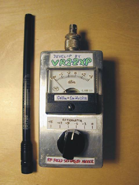 RF Field Strength Meter with Attenuator up to 200 MHz
The RF field meter unit is a great help to tune transmitters for best performance and output power. You can measure the radiated energy field and can easy tune the system for max output field strength maximum power.
This field strength meter comes with selectable attenuator. You can use it for measuring the antenna gain and pattern, compare different magnetic field strengths. See the following RF field strength meter schematic.
Posted on Friday, June 17, 2011 • Category: FM Transmitters
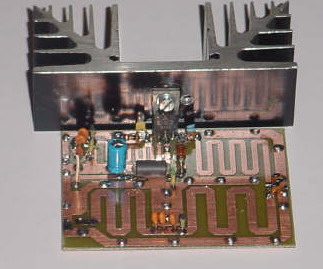 Here's 8W broadband FM RF amplifier using 2SC1971 VHF power transistor. The RF Amplifier PCB layout designed for FM broadband 88-108 MHz transmitters using microstripline technique. This 8W RF amplifier circuit provides an appropriate power boost for transmitters with an input of 500 mW.
Posted on Wednesday, June 15, 2011 • Category: Battery Chargers
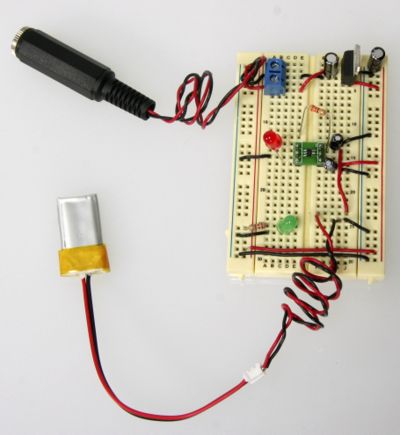 This is LiPo battery charger circuit based around the MAX1551 / MAX1555 chip from Maxim ICs. And it happens to be a very easy chip to use. I used the typical circuit from the datasheet and referred to the pin out to see which pin is what. I also used adapter board so that I could prototype the LiPo battery charger on a breadboard. The barrel plug towards the top goes into an LM7805 that can take 7-16V and regulates it down to 5V. Besides that, pretty simply stuff with only a handful of common components.
Posted on Tuesday, June 14, 2011 • Category: FM Transmitters
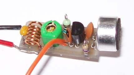 A very small home made FM transmitter Bug using a single transistor and with a transmission range of 200 meters. This FM transmitter Bug is very easy to build. The size of the circuit board is ONLY 22mm x 10mm.
Posted on Saturday, June 11, 2011 • Category: FM Transmitters
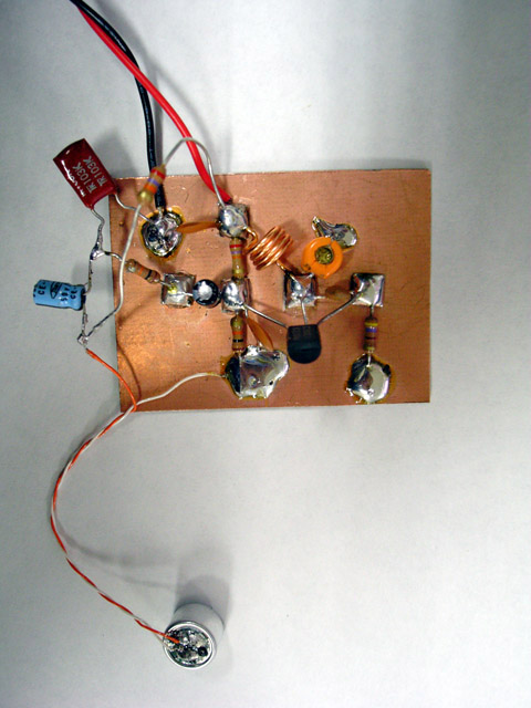 Here's how to build a simple FM Transmitter. This tiny transmitter has smaller radius of the service area, lower quality of the sounds and the relatively unstable frequency. These can be considered as a compromise to easily have your own transmitter for the time being or as a more positive choice. These "defects" are only from the perspective of conventional transmission such as "clear stereo sound to receive anywhere". Artist could change these to another directions. Whether or not, you can experience a convivial wireless imagination by this transmitter.
Posted on Thursday, June 9, 2011 • Category: FM Transmitters
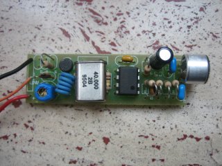 This micro spy PLL FM Transmitter transmits on the 160MHz frequency (if we use a 40MHz quartz) and therefore can be listened through a receiver tuned on this frequency. This circuit can be used to on various frequencies, for example on the FM band 88-108 just modifying some components, among which the quartz (25MHz).
Voice is detected by an electret microphone, then it is amplified and filtered by U1 pass-band in order then to be modulated from the carrier section, where through the varicap diode it "mixes" with the frequency generated by the quartz, that guarantees an adapted stability. Practically the modulating voltage is obtained applying the audio signal to the resonating circuit varicap diode that determines the carrier oscillation. The carrier frequency (160 MHz) must be greater than the modulating frequency (300-3300 Hz) audio band.
The transmission is on the fourth harmonic, therefore 160MHz, the oscillation frequency of the driver RF transistor Q1.
A small calibration is allowed acting on the L1 inductance and the C1 Trimmer Capacitor.
Posted on Thursday, June 9, 2011 • Category: PIC
 We love to read emails from our visitors, Please let us know by clicking here if you find any kind of bug/error in our site. We will fix it as soon as possible.
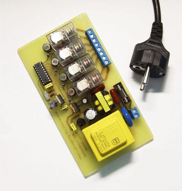
PIC Controlled Relay Driver
This circuit is a relay driver that is based on a PIC16F84A microcontroller. The board includes four relays so this lets us to control four distinct electrical devices. The controlled device may be a heater, a lamp, a computer or a motor. To use this board in the industrial area, the supply part is designed more attentively. To minimize the effects of the ac line noises, a 1:1 line filter transformer is used.
Posted on Wednesday, June 8, 2011 • Category: FM Transmitters
Mini FM transmitters take place as one of the standard circuit types in an amateur electronics fan's beginning steps. When done right, they provide very clear wireless sound transmission through an ordinary FM radio over a remarkable distance. I've seen lots of designs through the years, some of them were so simple, some of them were powerful, some of them were hard to build etc.
Here is the last step of this evolution, the most stable, smallest, problem-less, and energy saving champion of this race. Circuit given below will serve as a durable and versatile FM transmitter till you break or crush it's PCB. Frequency is determined by a parallel L-C resonance circuit and shifts very slow as battery drains out.
Circuit-Zone.com © 2007-2026. All Rights Reserved.
|
|
|