Circuit-Zone.com - Electronic Projects
Posted on Friday, May 6, 2011 • Category: Test and Measurement
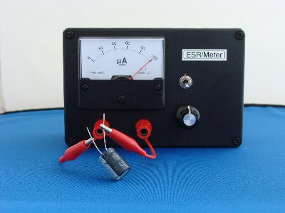
"ESR" stands for equivalent series resistance. ESR is one of the characteristics that defines the performance of an electrolytic capacitor. Low ESR is highly desirable in a capacitor as any ripple current through the capacitor causes the capacitor to heat up due to the resistive loses. This heating accelerates the demise of the capacitor by drying out the electrolyte at an ever increasing rate. Over the lifetime of a capacitor, it is not uncommon for the ESR to increase by a factor of 10 to 30 times or even go open circuit. Typical lifetime ratings for electrolytics are 2000-15000 hours and are very dependant on ambient operating temperature. As the ESR increases, the filtering operation of the capacitor becomes impaired and eventually the circuit fails to operate correctly.
Why are ESR Meters so Useful?
A typical capacitor checker measures the capacity (usually in micro farads) of the test capacitor. Some advanced units also test for leakage current. Most of these testers require that the capacitor be removed from the circuit. Unless the capacitor has totally failed, they will not detect a high ESR value. In a typical circuit, there may be 10's or 100's of capacitors. Having to remove each one for testing is very tedious and there is a great risk of damaging circuit boards. This tester uses a low voltage ( 250mv ) high frequency (150khz) A/C current to read the ESR of a capacitor in the circuit. The in circuit testing is possible because of the low voltage used for obtaining the measurement. The voltage is low enough that solid state devices in the surrounding circuitry are not activated and do not affect the low resistance reading we are attempting to obtain. A lot of capacitor checkers will be damaged if you happen to test a charged capacitor. This circuit is A/C coupled and will withstand up to 400vdc of charge on a capacitor (but watch your fingers!). The ESR checker will not detect shorted capacitors as they will read with a very low ESR value. If you are trouble shooting a circuit, you will have to use several instruments including your nose, voltmeter and oscilloscope to locate all the possible failure modes. My experience has found that the ESR meter catches about 95% of capacitor problems and potential problems.
Posted on Thursday, May 5, 2011 • Category: Stepper Motors
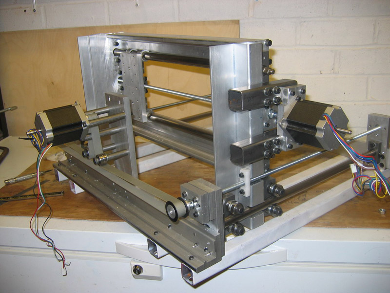 Stepper motors are everywhere in electronics these days. There are two main types of stepper motors:
1. Bipolar motors. These have two coils and are controlled by changing the direction of the current flow through the coils in the proper sequence. These motors have only four wires and cannot be connected to this kit. See our Kit 1406 for a Bipolar Stepper driver Kit.
2. Unipolar motors. These have two center-tapped coils which are treated as four coils. These motors can have five, six or eight wires. Five-wire motors have the two center-taps commoned internally and brought out as one wire (Fig 1). Six-wire motors bring out each center-tap separately. The two center-taps need to be commoned externally (Fig 2). Eight-wire motors bring out both ends of each coil. The four “center-taps” are joined externally to form one wire. In each case the center-tap(s) are connected to a positive motor power supply. Unipolar motors may be connect as bipolar ones by not using the ‘+’ wires.
A stepper motor has no brushes or contacts. It is basically a synchronous motor with the magnetic field electronically switched to rotate the armature magnet around.
The Internet is where to get all the explanation about steppers. Just google ‘stepper motor’ and you will find tens of sites. In particular, look for ‘Jones on Stepper motors’ (it comes up top of the list when I did it just now) and read it. If you look at the other references you will find that the circuit in this kit has been around for many years in various forms. The latest publication was in Silicon Chip, 5/2002, and I have based this circuit on it.
Posted on Thursday, May 5, 2011 • Category: Headphone Amplifiers
 If you built our 20W Class-A Stereo Amplifier described last year, you will be aware that it lacks a headphone socket. Similarly, many hifi valve amplifiers also lack a headphone socket, the assumption being that a true hifi enthusiast will want to listen via good-quality loudspeakers.
A headphone output was not included in the Class-A Stereo Amplifier because it would degrade its superb audio performance. Both the wiring paths and the general circuit layout are critical factors in the design and any changes, however slight, can cause big changes in the signal-to-noise ratio and harmonic distortion figures of the amplifier.
Click for larger image
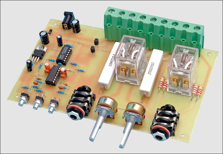
Fig.1: the Stereo Headphone Adaptor connects between your stereo amplifier and the loud-speakers and can drive two pairs of headphones.
If you do want to listen via headphones, a far better option is to build the simple Stereo Headphone Adaptor presented here. It connects directly to the amplifier’s speaker terminals and switches the loudspeakers and stereo headphone sockets using two DPDT (double-pole, double-throw) relays, so there’s no chance of it degrading the audio performance.
Posted on Thursday, May 5, 2011 • Category: Sensors
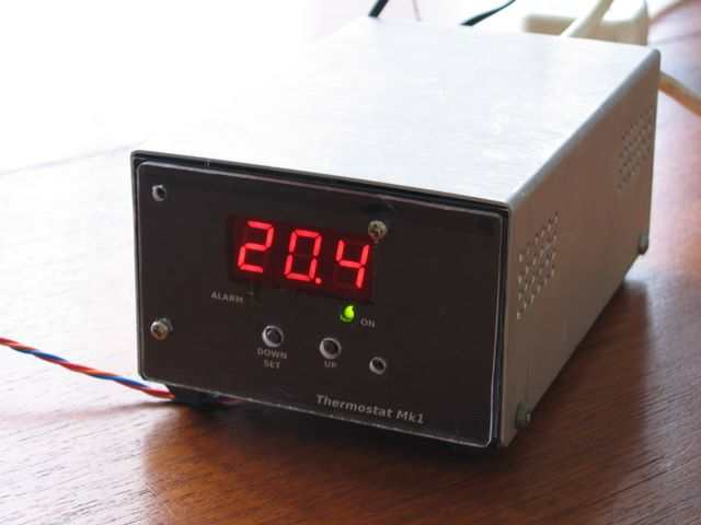 I needed to replace two old, unreliable thermostats for controlling the heating and cooling for a large garden shed.
Commercial basic digital thermostats are available quite cheaply, but some lack the ability to control heavy loads or have the extra features that I require for saving energy when the door is often left open or to indicate temperature being out of range etc.
I like the PIC18F1320 microcontroller used in my previous project - so decided to use it again in a very similar design to drive three multiplexed LED displays and read the temperature from a Dallas/Maxim DS18x20 "1-Wire" digital sensor.
Posted on Wednesday, May 4, 2011 • Category: Timer Circuits
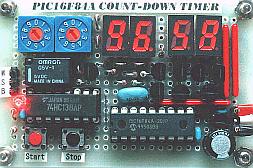 Here is a 60 minute countdown timer that can be used as an exposure timer for UV light boxes, photography, egg timer, and many other projects where counting or delay is necessary. The heart of the countdown timer is PIC16F84A chip and 4 digit character LED display. The relay is energized after the count down timer goes down from specified minute and second until zero, and can both turn devices on or off. See the link for details and schematic.
Posted on Wednesday, May 4, 2011 • Category: Sensors
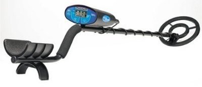 Nowadays, metal detection has become a hobby of many people. Besides as a funny and interesting hobby for them, they also wished indeed a treasure that is embedded in the soil when excavated. For this one hobby, you have to have a tool known as a metal detector.
To undergo this hobby is quite expensive to buy. But for those of you who want to try to make yourself a metal detector, the following will be presented a simple schematic that relates to metal detection.
The operation of metal detector is based on superheterodying principle, which is generally used in a heterodyne receiver. This circuit uses two RF oscillators. Both oscillator frequency is fixed at 5.5 MHz. The first RF oscillator comprises transistor T1 (BF 494) and 5.5 MHz ceramic filter commonly used in TV sound-IF section.
The second oscillator is an oscillator Colpitt realization with the help of the transistor T3 (BF494) and inductor L1 (follow the details of construction) was driven by trimmer capacitor VC1.
Posted on Tuesday, May 3, 2011 • Category: Headphone Amplifiers
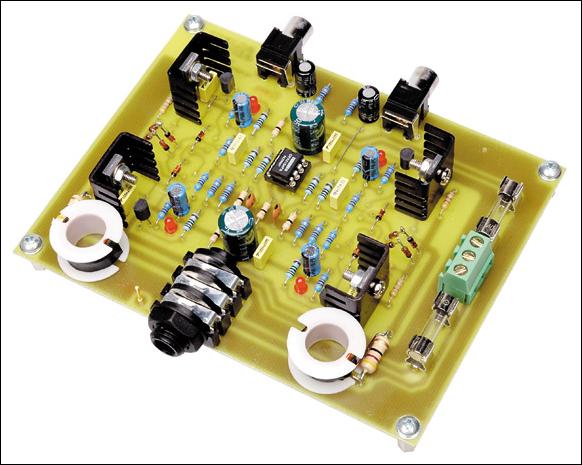 This is a dual/stereo headphone amplifier with high quality audio built around OPA2134. This headphone amplifier can drive high or low impedance phones with low noise and distortion. When used with line level signals from CD/MP3 players, etc., requiring only a power supply and volume potentiometer.
Many high-power amplifier audio designs have already provided an output for headphones. To support simple headphones, additional circuitry is required by adding only two resistors in series with the loudspeaker output to limit the drive current and protects the phone that in terms of reinforcing failure.
Considering its simplicity, this scheme works well resistive limit, although it will cause distortion if the load is non-linear - a prospect that may be most headphones. In addition to eliminating potential sources of distortion, there are a number of other reasons why you might consider to build a separate headphone amplifier.
Posted on Monday, May 2, 2011 • Category: Test and Measurement
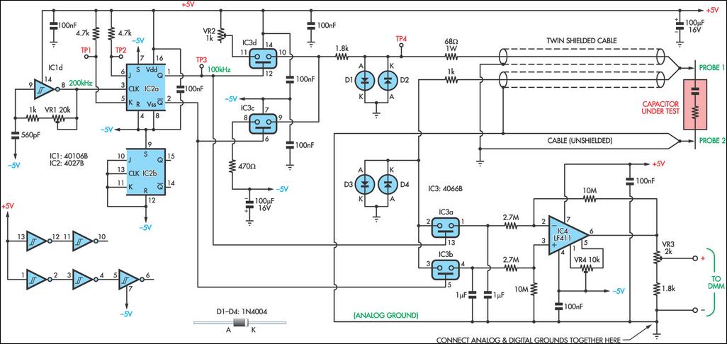 As electrolytic capacitors age, their internal resistance, also known as "equivalent series resistance" (ESR), gradually increases. This can eventually lead to equipment failure. Using this design, you can measure the ESR of suspect capacitors as well as other small resistances. Basically, the circuit generates a low-voltage 100kHz test signal, which is applied to the capacitor via a pair of probes. An op amp then amplifies the voltage dropped across the capacitor’s series resistance and this can be displayed on a standard multimeter. In more detail, inverter IC1d is configured as a 200kHz oscillator.
Its output drives a 4027 J-K flipflop, which divides the oscillator signal in half to ensure an equal mark/space ratio. Two elements of a 4066 quad bilateral switch (IC3c & IC3d) are alternately switched on by the complementary outputs of the J-K flipflop. One switch input (pin 11) is connected to +5V, whereas the other (pin 8) is connected to -5V. The outputs (pins 9 & 10) of these two switches are connected together, with the result being a ±5V 100kHz square wave. Series resistance is included to current-limit the signal before it is applied to the capacitor under test via a pair of test probes. Diodes D1 and D2 limit the signal swing and protect the 4066 outputs in case the capacitor is charged.
Posted on Monday, May 2, 2011 • Category: Remote Control
 This circuit consists of Transmitter and Receiver section. The circuit can be used to control home appliances within a range of 30 meters. In open area, you can expect a range of 100 meters. The circuit comprises HT12 Encoder and Decode IC's. HT12 Encoder is used in the transmitter (remote) circuit where as HT12E is used in receiver circuit. The Encode IC encodes the 4 bits of data and transmit it serially to to RF Transmitter module. These 433Mhz transmitter and receiver modules operate using ASK Modulation.
Posted on Sunday, May 1, 2011 • Category: Remote Control
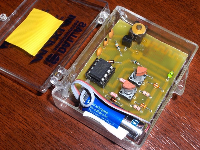
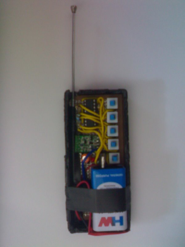
This is another remote control for my RF light switch. Pretty much the same as before but on a smaller PCB. Also ended up putting it in an old Maxim sample box.
I found a couple of button nubs in my junk box so decided to go with those. Even so I had to raise the buttons with pieces of rubber. A piece of tape keeps the buttons from falling out when the box is opened and also adds some tolerance for misalignment.
Circuit-Zone.com © 2007-2026. All Rights Reserved.
|
|
|