Circuit-Zone.com - Electronic Projects
Posted on Tuesday, April 13, 2010 • Category: Amplifiers
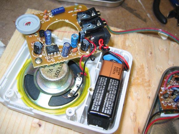
This simple amplifier shows the LM386 in a high-gain configuration (A = 200). For a maximum gain of only 20, leave out the 10 uF connected from pin 1 to pin 8. Maximum gains between 20 and 200 may be realized by adding a selected resistor in series with the same 10 uF capacitor. The 10k potentiometer will give the amplifier a variable gain from zero up to the maximum.
Posted on Tuesday, April 13, 2010 • Category: USB Circuts
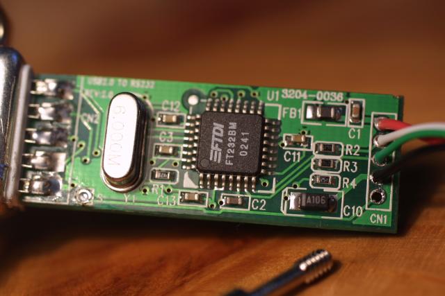 We employ two UART boards in the course, one which can be connected to the serial connector of the PC (UART-RS232), and a second that can be connected to a USB port (UART-USB). The former is used in the lab and is part of the standard take-home equipment. The latter is part of the (limited!) number of take-home targets for students who are working on a Laptop without serial connector. In both cases, communication is done with the UART module of the microcontroller. In the case of the normal UART board, the MAX232 simply transforms the voltage levels to RS-232 standards (± 3-15V; in our case 12V, with LOW=+12V and HIGH=-12V). In case of the UART-USB, the FT232BM transforms the UART protocol to the USB protocol. This is transparent to the controller, which communicates over the normal TX and RX pins.
Posted on Tuesday, April 13, 2010 • Category: Audio DAC
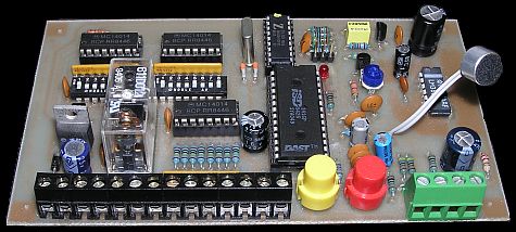 The voice messages are recorded into the on-board microphone, then each message can be individually triggered by an external signal. The inputs can respond to simple electrical contacts, logic levels or voltages, and all inputs are debounced to prevent false triggering by electrical noise. Each message can be arranged to play once on a selected change of input state (high-to-low or low-to-high), or to repeat continuously until the trigger condition is removed. These options are selected by DIP switches.
Posted on Monday, April 12, 2010 • Category: PIC
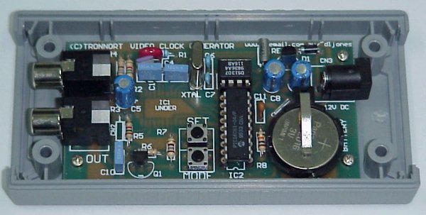 Perfect low cost solution for: * New video security
installations * SSTV transmitters * Amateur video * Existing installed security installations * Scientific experimentation monitoring * and any other application that needs the time and date recorded on an image!
Posted on Monday, April 12, 2010 • Category: Test and Measurement
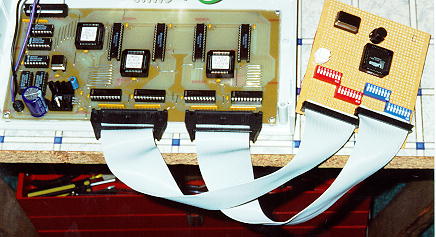 This project was published in Electronics Australia in Oct/Nov 96. It is a 32 Channel, 40Mhz, fully PC controlled TTL/CMOS logic analyzer with internal/external triggering and trigger delay. Internal triggering is fully maskable (High/Low/Don't Care) on all 32 channels. The whole things fits on one single sided PCB with virtually no wiring!
Posted on Monday, April 12, 2010 • Category: Frequency Wave Generators
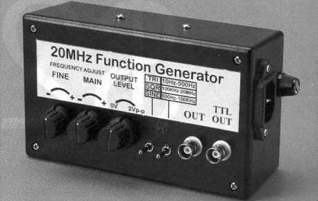 The High Speed Function Generator was published in the professional electronics section of the Aug 1996 issue of Electronics Australia, and has proven to be extremely popular. The kit is no longer available from any of the kit suppliers. The project is capable of generating 20MHz or greater Sine, Square, Triangle, and TTL waveforms.
Posted on Saturday, April 10, 2010 • Category: PIC
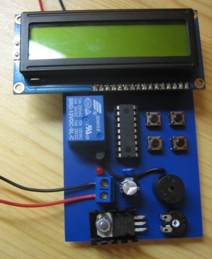 If you need an UV LED timer, or a timer for any other purpose you may be interested in the UV LED Controller that was constructed using a PIC 16F628A Microcontroller. There is a schematic and code available however the original project was not documented in English. Have a look at the Google translation that did a decent job of translating this one.
Posted on Saturday, April 10, 2010 • Category: PIC
 The new PIC18F2550 Project Board was designed as the development platform for student projects. The board features MCU: PIC18F2550 with external xtal, ADC: one channel 0-2.5V sigma-delta converter, Linear Technology LTC2400/LTC2420, 6-channal 10-bit ADC 0-5V, Display: Two connectors for text LCD or GLCD, USB: onchip USB port with type B connector, Power supply: onboard low dropout regulator, rechargeable battery, Code programming: 10-pin header for In Circuit Loader. The board platform is suitable for developing the microcontroller based instrumentation. Students may build the signal conditioning board, plugs it to PIC project board, develops the code and programs it with loader cable easily.
Posted on Saturday, April 10, 2010 • Category: FM Transmitters
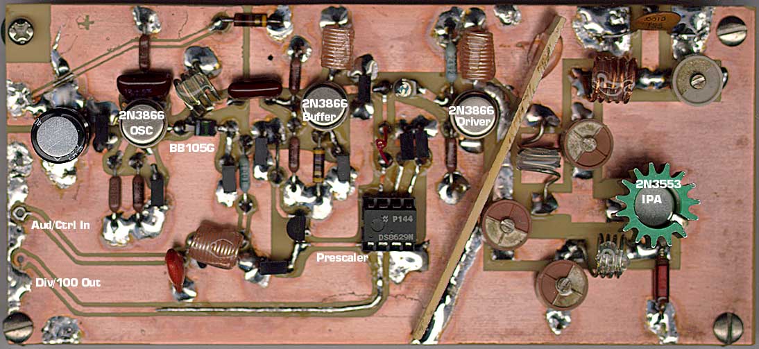 This is a PLL controller that works with the VCO/Modulator that I designed. Use these two modules together for a complete baseband-capable exciter unit. This PLL controller features a rock-stable crystal controlled reference, in conjunction with a programmable dividing network which allows the transmitter to be tuned in 100Khz steps from 79.9Mhz to 109.7Mhz by means of digital thumbwheel switches. Oscillator, buffer and driver stages use 2N3866 power RF transistor and output stage used 2N3553 4W RF transistor,
Posted on Saturday, April 10, 2010 • Category: USB Interface Adapters
The UBW board is a small board that contains a Microchip PIC USB-capable microcontroller such as PIC18F2455, PIC18F2550, PIC18F4455 or PIC18F4550 and headers to bring out all of the PICs signal lines and board is powered from the USB connection. I designed this board to be a simple parallel port replacement tool for Bruce Shapiro for use in his bits-to-bytes-to-bots class. Apologies to all other 'Whacker' projects like EDTP's Packet Whacker for stealing a great name . All tools used to design this project are free, and the design is open to anyone to use for whatever they wish.
Circuit-Zone.com © 2007-2026. All Rights Reserved.
|