Circuit-Zone.com - Electronic Projects
Posted on Thursday, August 5, 2010 • Category: FM Transmitters
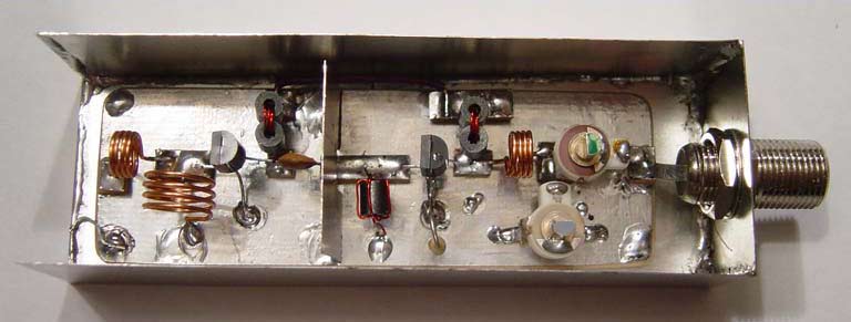
This is an excellent 50mW Hi-Fi PLL FM Stereo Transmitter that features BH1417 chip. ROHM's new Japan has BH1417 is one of the most simple and practical integrated circuits, which combines phase-locked loop circuit, stereo encoder circuit, transmitter circuit, as well as other additions. Pre-emphasis circuit, limiter circuit and low pass filter can significantly improve the sound quality. The total harmonic distortion up 0.3%, stereo separation to 40dB, RF output level is 100dB. BH1417F is an excellent new IC chip, this circuit improves signal to noise ratio (S / N) of pre-emphasis circuit to prevent signal over emphasized limiting circuit, the control input signal frequency low-pass filter circuit (LPF), generate stereo stereo composite signal modulation circuit, FM transmitter phase-locked loop circuit (PLL) component. BH1417F excellent frequency characteristics, it can achieve 40dB of isolation, transmitted sound quality is similar to local FM radio stations.
Posted on Thursday, August 5, 2010 • Category: FM Transmitters
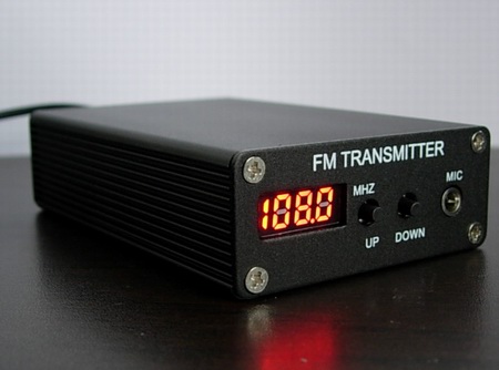 5W PLL Stereo FM Transmitter features PLL synthesized drift free operation with high quality BH1415 chip. 5W RF output power is achieved with 2SC1971 6W transistor in the output stage. Front panel digital control comes with LED display and case is made high quality aluminum. The board features EMI filtering on audio and power inputs and comes with Microphone and Audio inputs. Once transmitter is turned on it starts broadcasting with previously selected frequency. Overall this 5W PLL Stereo FM Transmitter provides professional broadcast audio quality and rivals commercial broadcasts.
Posted on Wednesday, July 28, 2010 • Category: Headphone Amplifiers
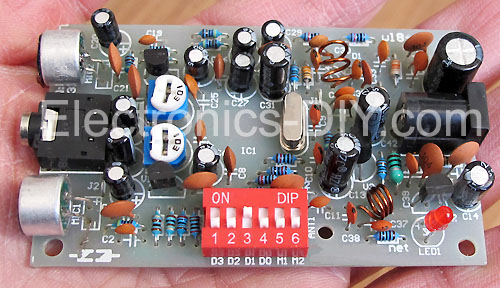
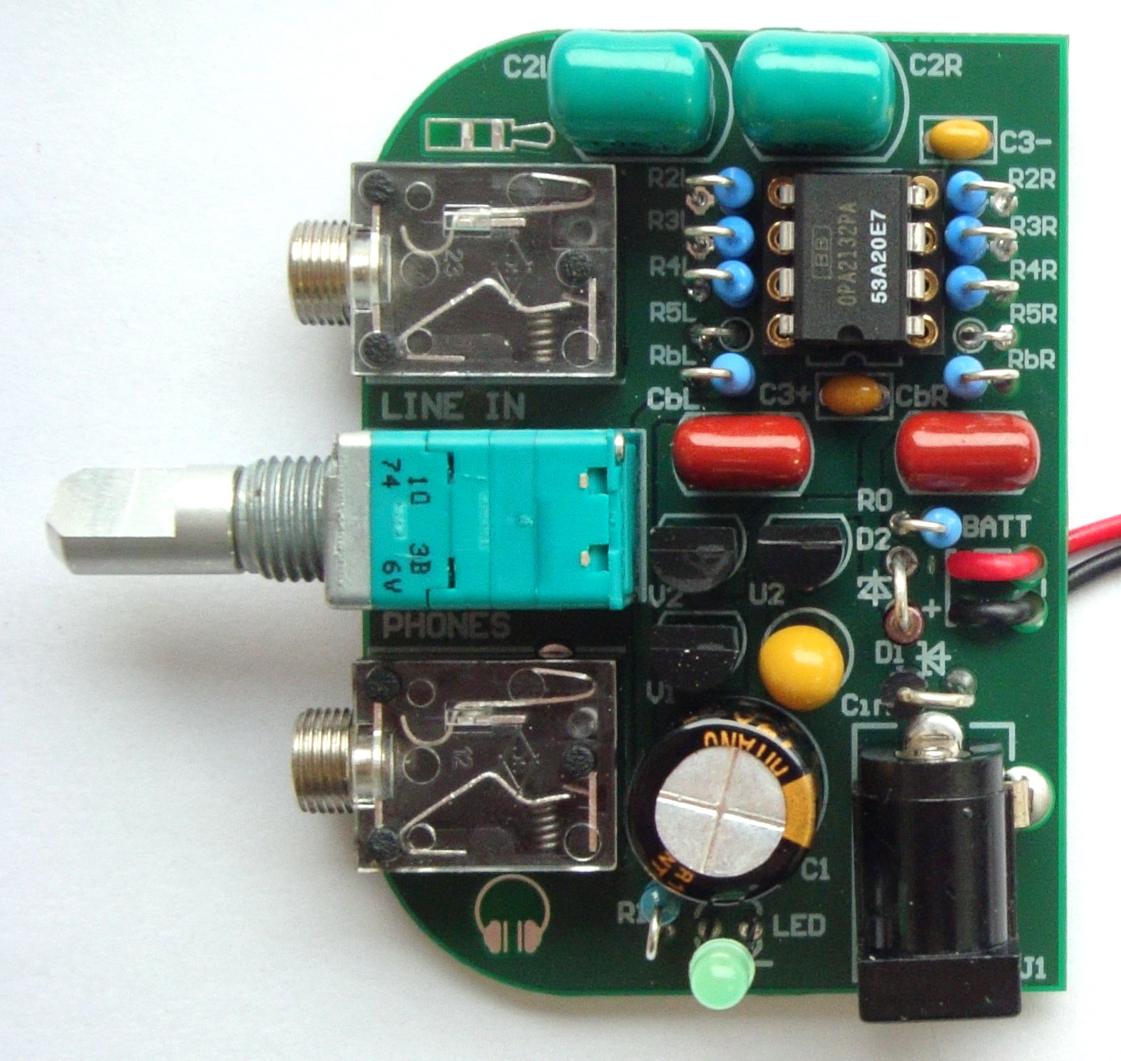 This is an article about my new PCB design for HiFI headphone amplifier using audiophile OPA2132 OP-AMP chip. Main feature is that the new PCB fits exactly to the classic Altoids tin-can. This new headphone amplifier incorporates moreover bass-boost circuit and constant current charger for 9V battery.
Posted on Wednesday, July 28, 2010 • Category: Audio DAC
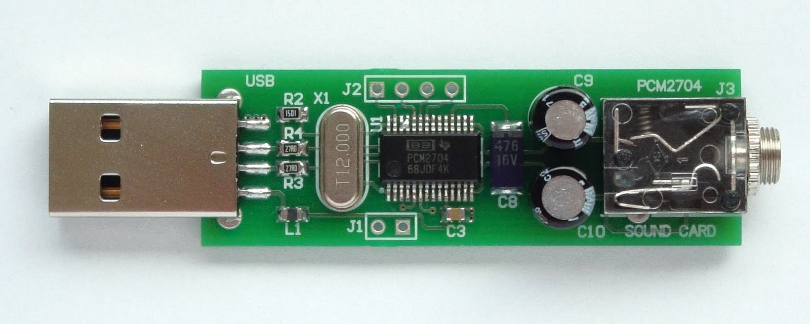 This device is fully functional sound card for PC. The main advantage of using PCM2704 against PCM2702 is much easier construction. As you can see on the block diagram it has built-in 5V and 3.3 voltage regulator, HID interface (MUTE, VOL+, VOL-), S/PDIF output. The circuit can be powered directly from USB port. Next advantage is that the output DAC is able to drive directly 32ohms headphones, but the output power is only 12mW. For all details please refer to the PCM2704 datasheet.
Posted on Thursday, July 15, 2010 • Category: FM Transmitters
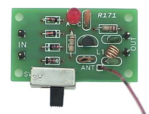 This Phone FM transmitter connects in series to your telephone line and transmits the telephone conversation over the FM band when you pick up the telephone handset. Transmitted signal can be tuned by any FM receiver. The circuit includes an "On Air" LED indicator and also provides a switch which can be used to turn off the transmitter. A unique feature of the circuit is that no battery is needed to operate the circuit since power is taken from the telephone line. The transmitter uses only a short piece of wire aerial about 4" / 10 cm long to transmit the signal and some of the RF signal is also radiated through the telephone line itself. The circuit might be used to share or record conversations, but is not intended for illegal use.
Posted on Thursday, July 8, 2010 • Category: FM Transmitters
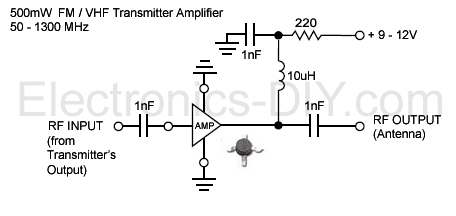 This is a high performance low noise 500mW amplifier / booster for all low power FM transmitters such as BA1404, BH1417, BH1415, 433MHz transmitter modules, etc. The amplifier chip is an integrated circuit containing multiple transistor stages and all other parts conveniently within a single small package. Boosting your FM transmitter has never been easier and the output signal can also directly drive 2n4427 or 2n3886 transistors for 1W or 5W of RF output power.
Posted on Saturday, June 12, 2010 • Category: FM Transmitters
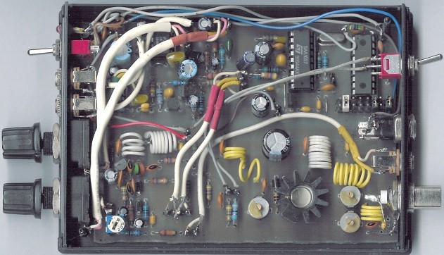 This small FM transmitter includes a limiter, a microphone amplifier and a PLL digital tuning. All the parts are placed on one circuit board. The RF power is switchable between 1W and 0,2W.
The schematic diagram is divided into three parts: RF part (numbered from 1), PLL (numbered from 30) and audio part (numbered from 50).
Posted on Saturday, June 12, 2010 • Category: FM Transmitters
 The TX500 is a simple to build 500mW FM Transmitter. It consists of three blocks; modulator / oscillator, two stage 500mW VHF amplifier and LED based power meter. The TX500 allows to transmit audio signals to FM band at frequencies from 88 MHz to 108 MHz. Due to the very low power consumption of less than 100mA the circuit may be perfectly powered by using 9-12V battery or power supply if you prefer. The circuit has been divided into separate stages so that it is be better for everyone to understand how every part works independently.
Posted on Saturday, June 12, 2010 • Category: FM Transmitters
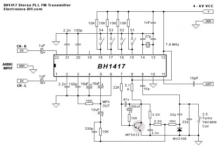 BH1417 is a latest FM Transmitter IC from RHOM that includes a lot of features in one small package. It comes with pre-emphasis, limiter so that the music can be transmitted at the same audio level, stereo encoder for stereo transmission, low pass filter that blocks any audio signals above 15KHz to prevent any RF interference, PLL circuit that provides rock solid frequency transmission (no more frequency drift), FM oscillator and RF output buffer.
Posted on Saturday, June 5, 2010 • Category: Antennas
To improve signal transmission or reception in specific directions, basic elements, either vertical or horizontal, can be combined to form arrays. The most common form is the Yagi-Uda parasitic array commonly referred to as a Yagi array or beam.
It consists of a driven element which is either a simple or folded dipole and a series of parasitic elements arranged in a plane. The elements are called parasitic because they are not directly driven by the transmitter but rather absorb energy from the radiated element and re-radiate it.
Circuit-Zone.com © 2007-2026. All Rights Reserved.
|