Circuit-Zone.com - Electronic Projects
Posted on Friday, February 19, 2010 • Category: FM Transmitters
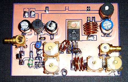
This RF power amplifier is based on the transistor 2SC1970 and 2N4427. The output power is about 1.3W and the input driving power is 30-50mW. It will still get your RF signal quit far and I advice you to use a good 50 ohm resistor as dummy load. To tune this amplifier you can either use a power meter/wattmeter, SWR unit or you can do using a RF field meter.
Posted on Friday, February 19, 2010 • Category: FM Transmitters
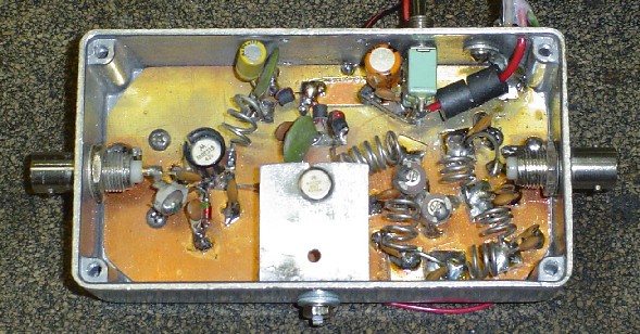 This design is a 2 stage amplifier that has about 17db of gain, suitable for an input of 50 to 100 MW. Its basically a Veronica 5 watt vco transmitter, without the vco. The transistors are a 2N4427 and a MRF237. Output power is 2.5 to 5 watts, depending on input drive and dc voltage. At 13.7 vdc with 50 MW of drive, the output was 2.5 watts. The maximum dc voltage recommended is about 15-16 volts.
Posted on Saturday, October 31, 2009 • Category: Audio DAC
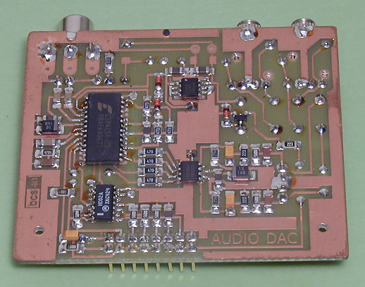 The described device is used to convert the digital signal format S / PDIF (AES3) to analog signal. It can be used for any device with an output of uncompressed digital audio (CD or DVD players DVD, minidisc, PC sound card, CD-ROM). The device does not signal processor, and therefore not able to play compressed or encoded multichannel signal (AC3, MP3, respectively. Mpeg). Separate transmitter can improve the signal to noise ratio and to reduce interference, which is especially true for PC sound card.
Posted on Saturday, October 31, 2009 • Category: Battery Chargers
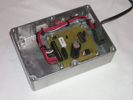 This cheap and easy to build NiCd/NiMH Battery Charger is suitable for automatically charging a wide range of batteries for many applications. Proper chargers are usually expensive and cheap chargers supplied with the original equipment often incorrectly charge the cells and dramatically shorten their life. This 'intelligent' charger was designed for high current and rapid charge applications such as cordless power tools and model racing cars. These battery packs are expensive and sometimes difficult to purchase. This charger uses the cell manufacturer's recommended charge method, to safely and quickly charge batteries.
Posted on Saturday, October 31, 2009 • Category: FM Transmitters
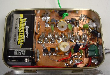 The transmitter uses 2 MPSH10 (equiv BF494 or NTE229) transistors in a double-ended free-running voltage controlled oscillator (VCO) operating at half the output frequency on each side and combined at L2, which is tuned to the 2nd harmonic of the VCO and covers the 88-108 MHz range. A standard 9 volt battery is used for power and fits inside the tin. The mono audio input circuit is totally passive with 70us pre-emphasis provided and the audio quality is great.
Posted on Saturday, October 31, 2009 • Category: PIC
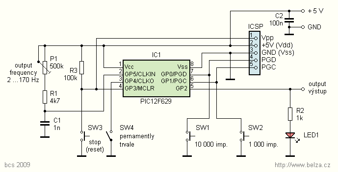 Circuit is very simple. The generator uses a PIC12F629 microcontroller with clock frequency set by an external RC. Output frequency can be set trimmer P1 in the range of about 2 to 170 Hz. Oscillator frequency can be adjusted if you change C1 capacitance. Pulses are generated with a period of 200 Tcy. All pulses are of equal length. Output frequency is 800 times lower than the frequency of the oscillator.
Posted on Thursday, October 29, 2009 • Category: FM Transmitters
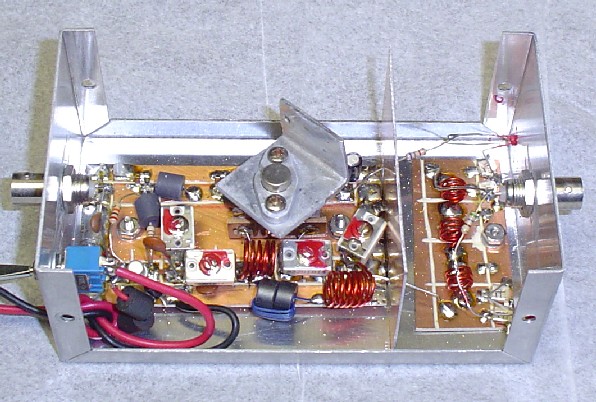 This is a 1 watt amplifier. This design is a 2 stage amplifier that has about 16db of gain, suitable for an input of 5 to 20 MW. The transistors are a 2N4401 and a 2N4427. At 13.7 vdc the most I could get out of the unit was 1/2 watt, you could probably raise the dc voltage to 16 volts and get more output but then a much better heatsink would be required. But for the sake of this project, we'll call it a 1/2 watt amplifier.
Posted on Tuesday, October 27, 2009 • Category: FM Transmitters
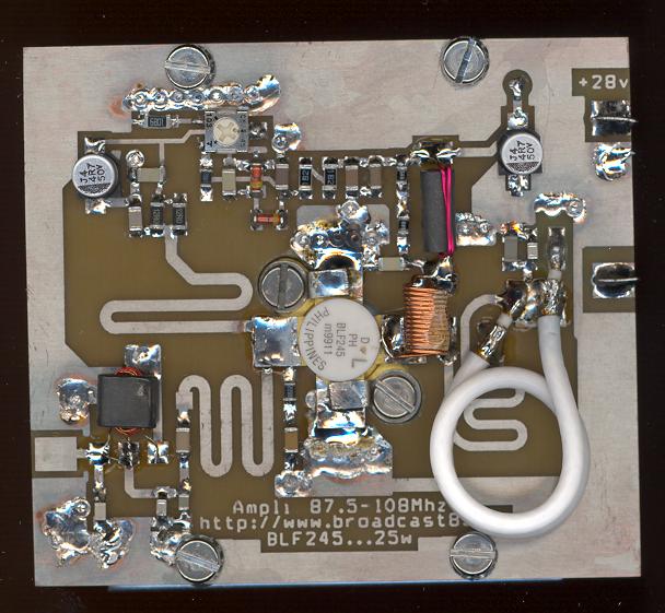 The achievement of this 30-watt amplifier has been designed to take place on a heatsink microprocessor PC equipped with its fans, the advantage of this method of cooling has been selected for the fact that it is not very common and expensive. The size of the printed circuit will adapt quite easily to the type of heatsink as you have available, if possible, because in many cases, those of recovery, the fans have already lived and the price of a model remains very affordable.
Posted on Tuesday, October 27, 2009 • Category: FM Transmitters
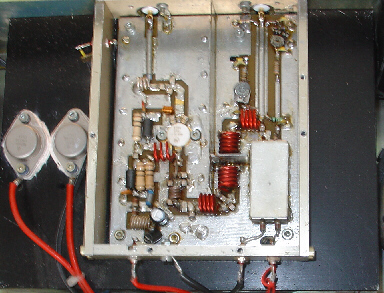 This Power amplifier is equipped with a bipolar transistor,the famous MRF317 As lots of FM amplifier application ,the power transistor is in a C class bias. All the impedance networks (Input & Output) have been determined by using the software: Mimp.EXE. A 9 elements low pass filter ensures that we meet at least a 60 dB rejection from the carrier.(RF Simulation with RFSIM99) The FM amplifier has a 10 dB gain with a 60 to 65% efficiency. The Input VSWR is around 1.4 and there's no problem to reach the max power in all the FM band.
Posted on Tuesday, October 27, 2009 • Category: FM Transmitters
Be "On Air" with your own radio station! BA1404 based transmitter is an exciting product that will broadcast high quality stereo signal in 88MHz - 108MHz FM band. It can be connected to any type of stereo audio source such as iPod, Computer, Laptop, CD Player, Walkman, Television, Satellite Receiver, Tape Deck or other stereo system to transmit stereo sound with excellent clarity throughout your home, office, yard or camp ground.
Circuit-Zone.com © 2007-2025. All Rights Reserved.
|