Circuit-Zone.com - Electronic Projects
Posted on Sunday, September 16, 2012 • Category: FM Transmitters
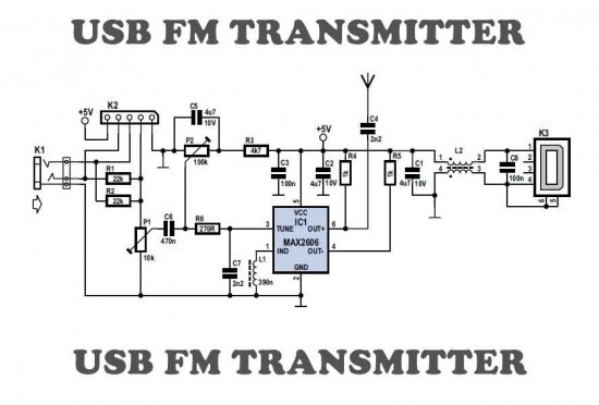
Here is a simple USB FM transmitter that could be used to play audio files from an MP3 player or computer on a standard VHF FM radio by connecting it to an USB port. The circuit use no coils that have to be wound. This USB transmitter can be used to listen to your own music throughout your home. To keep the fm transmitter circuit simple as well as compact, it was decided to use a chip made by Maxim Integrated Products, the MAX2606. This IC from the MAX2605-MAX2609 series has been specifically designed for low-noise RF applications with a fixed frequency. The VCO (Voltage Controlled Oscillator) in this IC uses a Colpitts oscillator circuit. The variable-capacitance (varicap) diode and feedback capacitors for the tuning have also been integrated on this chip, so that you only need an external inductor to fix the central oscillator frequency.
Posted on Monday, August 20, 2012 • Category: FM Transmitters
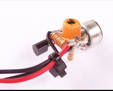 This easy to build FM transmitter bug can transmit voice to exceptionally good range. Tune trimmer to hear the signal to your near radio. Transmitter frequency range is 88-108 MHz. Max current consumption is 30mA. You can power the fm transmitter bug with a 9Volt Battery, or you can plug a power supply to feed in 9-12 Volts. That bug will pick even a low whisper or even the sound of a breath well far from the microphone. Great spy transmitter equipment.
Posted on Saturday, June 23, 2012 • Category: FM Transmitters
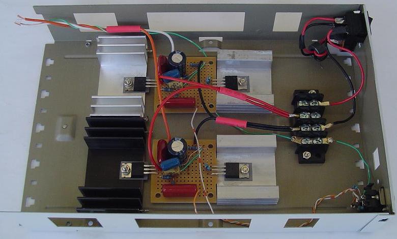
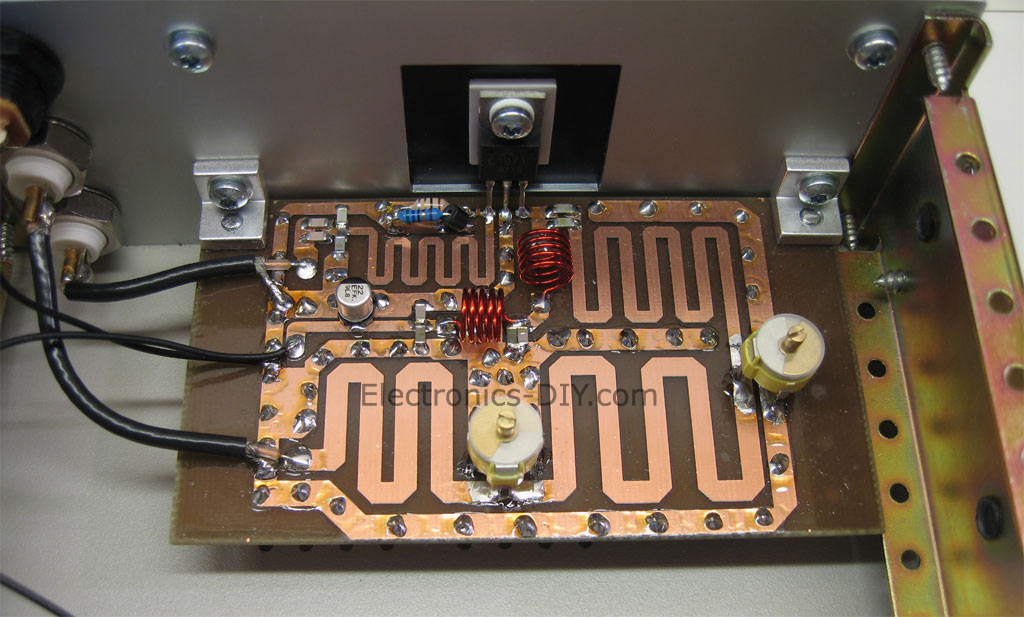 After building FM transmitter I decided to build a 6W RF Transmitter amplifier for the FM band to get more power and we chose to copy a 6 Watt design built around 2SC1971 RF power transistor. We were not satisfied with finished result and decided to replace the fixed capacitors around the pcb inductors with variable capacitors, this is much better and possible to tune to your transmitter frequency.
Posted on Friday, June 15, 2012 • Category: Antennas
 This HD TV UHF wideband amplifier(Ultra High Frequency amplifier) has a total gain of 10 to 15 dB in the 400 – 850 MHz domain frequency so it can be used where the tv signal is weak.
For this UHF antenna tv amplifier to work correctly you need to cut the components pins as short as possible. C1, C2, C6, C7 are SMD type ( surface mounted ). This antenna tv amplifier or uhf wideband amplifier need to be build inside of a metal box and then connected close to the tv antenna.
Posted on Sunday, June 10, 2012 • Category: Amplifiers
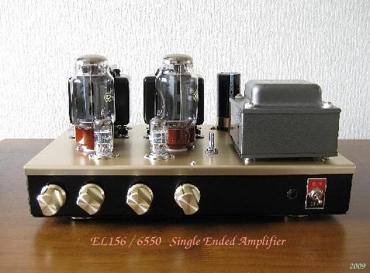 Single Ended Valve Triode Amplifier has not same tone with Push Psu Amplifier. Over 90% of Amplifiers are push pull, and push pull amplifier does not 2nd harmonic and off course
does not get 2nd 4th, 6th harmonic vs SE has 2nd, 4th, 6th harmonic. Push pull has minor distortion than SE Amplifier.2nd harmonic is make good tone for Music.not too much and not less than.feel good sound get from Single Ended Amplifiers with high efficiency speakers from 88dB/m to 100dB/m. I means Single Ended Amplifier
is almost Single Ended Triode Amplifier.or Penthode but wired Triode. Tone is Different.good for Jazz and
small room Classic.
Posted on Friday, June 8, 2012 • Category: FM Transmitters
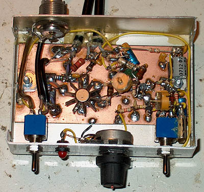 The 1 watt 20 meter QRP transmitter with VXO. This is a nice QRP transmitter that can be used in combination of one of the simple receivers.
Normally these designs have only two transistors: one is the X-tal oscillator and the second the final amplifier. A good example is my first QRP rig that is also described somewhere on this site. Here the VXO (Variabele X-tal Oscillator) has a tuning range of 16 kHz. This VXO is buffered with an extra driver stage for a better frequency stability and a varicap diode is used instead of a variabele capacitor. An extra transistor is added for keying the transmitter with a low keying current.
What you can do with such a simple 1 watt QRP power transmitter.
This is a real low power transmitter, so do not expect that you can do everything with it but...
When conditions are normal, you can easily make many QSO's during one afternoon with stations with distances upto 2000 km with a simple inverted V wire dipole antenna! From Europe, I did even make QSO's across the Ocean!
Posted on Tuesday, May 29, 2012 • Category: FM Transmitters
 This PLL transmitter is controlled and the frequency is very stable and can be programmed digitally. Transmitter will work 88-108 MHz and output power up to 500mW. With a small change can set the frequency of 50-150 MHz. The output power is often set to several watts with transistors. So therefore I decided to build a simple transmitter with great performances. The frequency of this transmitter can easily be changed by software and space / compress air coil. This transmitter is the oscillator colpitts. Oscillator is a VCO (voltage controlled oscillator) which is set by the PLL circuit and PIC micro controller. This oscillator is called the Colpitts oscillator and voltage controlled to achieve the FM (frequency modulation) and PLL control.
Posted on Wednesday, May 23, 2012 • Category: Test and Measurement
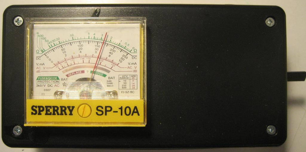 Field strength meter is extremely useful when working with RF devices. It can be used to quickly diagnose whether a transmitter circuit is working, and can be used to detect RF signals in the environment. The simplest field strength meter could be built with a tuned LC circuit and a germanium diode, just like the way of a building a crystal radio except replacing the ear piece with a high sensitivity current meter. While this approach fits the needs of most simple applications, it has a pretty narrow frequency range (~100 MHz) and requires tuning the LC circuit to the correct frequency before measurements can be made and the design can become complicated if wider frequency range tuning is desired.
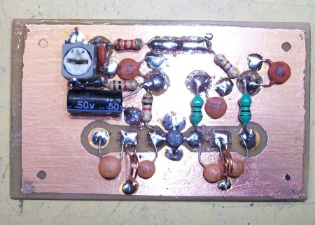
Posted on Monday, May 21, 2012 • Category: Power Supplies
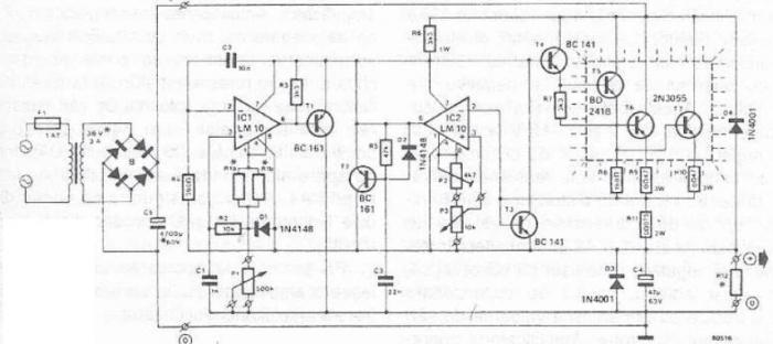 An 50v bench power supply can be made using electronic diagram below which is designed using LM10 op amp and 2n3055 transistors. This LM10 2n3055 50v bench power supply allows an output voltage regulation in a range between 0 and 50 volts and the output current can be limited to a maximum of 2A. Output voltage increases linearly with the amount of resistance potentiometer P1, while the current can be adjusted linear using potentiometer P3. Potentiometer P2 serves to regulate maximum output current (maximum value is 2A).
Posted on Wednesday, May 16, 2012 • Category: Amplifiers
Not thrilled with how a computer soundcard drove my 32ohm headphones so I decided to build myself class-A mosfet headphone amplifier. As with most of my projects, the goal was to keep it simple, keep cost down and try use some salvaged parts. This is a simple do-it-yourself (DIY) headphone amplifier project that is fashioned primarily after the Class A MOSFET Headphone Driver project by Greg Szekeres and to some extent Mark's DIY Class A 2SK1058 MOSFET Amplifier Project. The amplifier concept is simple and follows a typical single-ended class A circuit utilizing an active constant current source (CCS) in place of a passive resistor. A CCS doubles the efficiency of the circuit over that where a passive load resistor is used, bringing it to a maximum of 25%.
Circuit-Zone.com © 2007-2026. All Rights Reserved.
|
|
|