Circuit-Zone.com - Electronic Projects
Posted on Wednesday, April 28, 2010 • Category: FM Transmitters
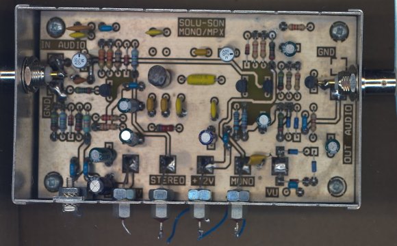
This map, armored also enables automatic MONO / MPX through a low-pass filter, even with a multiplex on its entry by using an ON / ON, panning, the whole spectrum MPX more RDS is sent to the synthesizer, on the other hand when it is in a position MONO, the low-pass filter is activated and share its cutoff frequency at 15 KHz, only modulation G + D is sent to the synthesizer, as 19 KHz. 19 KHz carrier, the signal multiplex and subcarrier 57 KHz is thereby eliminated, which provides ease of use for example in a string of issue relay tuner, if the link between the issuer Departure and receiver re-issue was not of good quality stereo, you sufficient to switch to mono to improve sound quality, you can then connect the RDS encoder at the re-issuer.
Posted on Wednesday, April 28, 2010 • Category: PIC
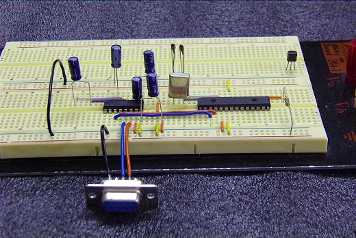
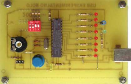 Manji broj proizvođača proizvodi IC kola za USB podršku. Najpoznatiji su: Cypress Semiconductor, FTDI, Philips i drugi. Microchip je 2000 godine proizveo mikrokontrolere PIC16C745 i PIC16C675 koji su imali podršku za USB komunikaciju i tako se pridružio ostalim proizvođačima. Ovi mikrokontroleri podržavaju USB 1.1 standarad, odnosno USB sa brzinama rada do 1.5 MBs. Nova serija Microchip-ovih mikrokontrolera urađenja u flash tehnologiji PIC18F2445/2550/4455/4550 je podržala USB 2.0 standrad. Ovo su moćni mikrokontroleri sa brzinama takta i preko 40Mhz i veličinom programske memorije od 32K reči. O stanadardima za USB možete na sajtu http://www.usb.org. Upravo na ovim mikrokontrolerima urađen je interfejs sa USB komunikacijom.
Posted on Wednesday, April 28, 2010 • Category: Battery Chargers
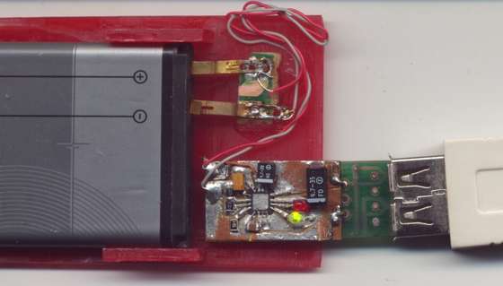 This is a charger for lithium ion batteries which takes its power from the USB port of a computer.
It uses the MCP73861 or MCP73863 Li-ion battery charger chip manufactured by Microchip.
Microchip MCP73861 or MCP73863 are advanced, fully-integrated, single-cell Li-Ion/Li-Polymer charge-management devices allow these peripherals to utilize the full power of the USB port.
Posted on Wednesday, April 28, 2010 • Category: Battery Chargers
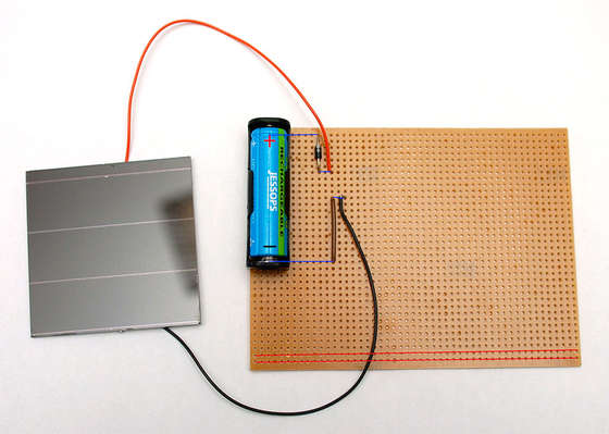 This instructable will show you how to make your own solar battery charger from very simple components. It is taken from my documentation provided with a kit I supply - you should easily be able to source the same components yourself of course.
Posted on Wednesday, April 28, 2010 • Category: Power Supplies
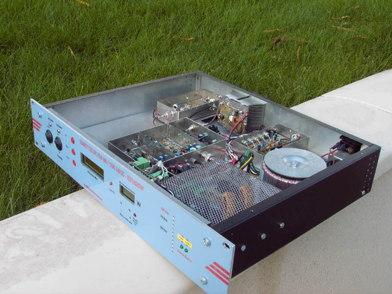 Power supply used for professional FM broadcasting transmitter.
Posted on Tuesday, April 27, 2010 • Category: Amplifiers
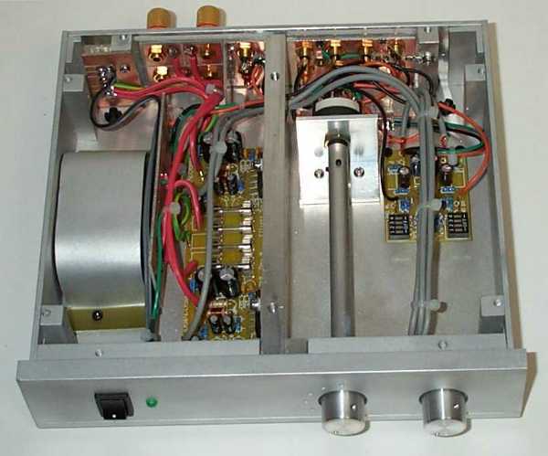 The amp is based on the Project 19 PCB, so uses a pair of LM3876 (or LM3886) power opamps, run from a ±35V supply. I used a cut-down P88 preamp PCB because I only wanted one preamplifier stage, but the entire board can also be used. Alternatively, the P19 amp can be run at higher gain than normal, alleviating the need for a preamp at all. The down side of this is that the noise level will be higher, and background noise may be audible with efficient speakers and/ or very quiet surroundings.
Posted on Tuesday, April 27, 2010 • Category: Battery Chargers
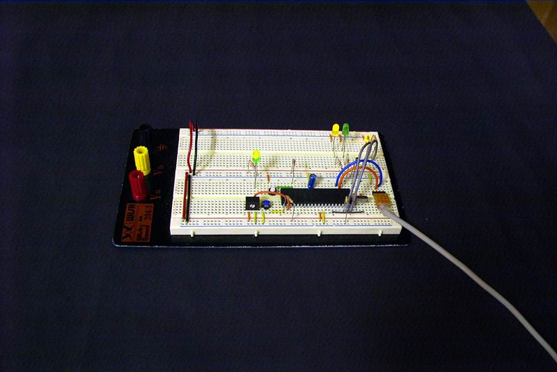
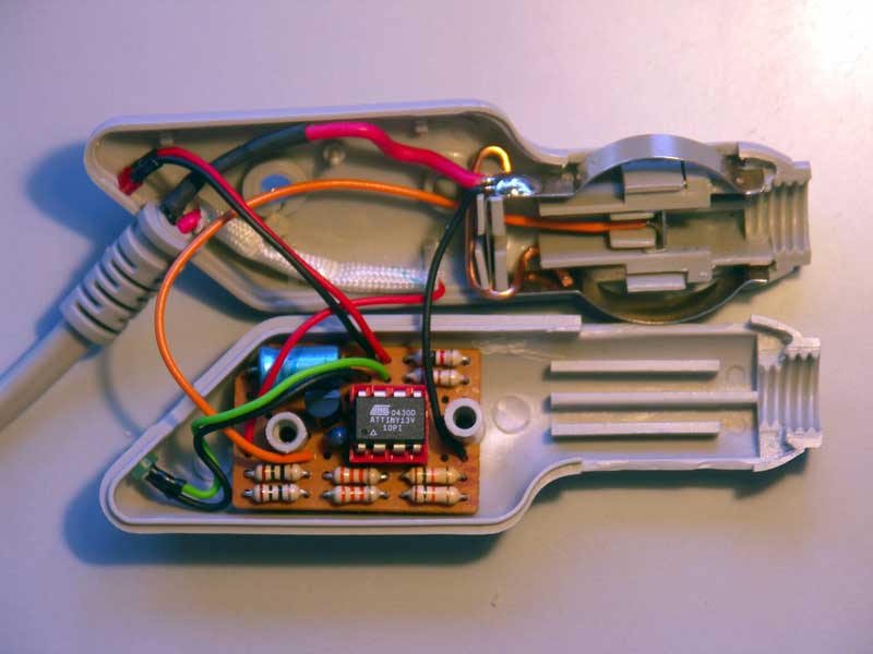 Batwatch is a simple monitor for a solar panel battery charger, using an Atmel ATtiny13V. It periodically measures the charge current and battery voltage, and shows them by blinking two LEDs. I built this circuit into the plug of a VW solar charger panel that is used to prevent a discharge of the battery when a car is not used for some time. A modern car contains a large amount of electronics, and a quiescent current of 40-50mA (about 1Ah per day!) is considered "normal".
Posted on Tuesday, April 27, 2010 • Category: PIC
When the device is connected to the computer, a Virtual COM Port (VCP) will be created. This is shown at the Device Manager Window under Ports(COM & LPT). In this case, COM5 was created when the PIC18F4550 was attached to the USB Port. It may be interesting to note that if you plug in your PIC in different USB ports, the VCP created will be different.
Posted on Tuesday, April 27, 2010 • Category: AVR
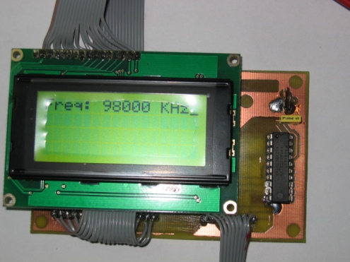
This is the transmitter PLL module with ATMega8, MC145170 and 16x4 LCD Display.
Posted on Tuesday, April 27, 2010 • Category: PIC
The quickest way to display something is probably sending the data to the computer to be displayed on the monitor. One of the ways to do this is to use the USART module on board the PIC Microcontroller by making use of the pins RC6 and RC7 which is also the TX and RX pins respectively when the SPEN bit on the RCSTA register is set.
Circuit-Zone.com © 2007-2026. All Rights Reserved.
|