Circuit-Zone.com - Electronic Projects
Posted on Tuesday, May 10, 2011 • Category: AVR
This AVR ISP original by ATMEL you can found on "AVR software
and technical Library - April 2003" CD-rom. It small component count I design new PCB and change some component that easy to build small PCB. The new firmware was writen by John Samperi for AT90S2313. This code can program more devices.
Posted on Monday, May 9, 2011 • Category: FM Transmitters
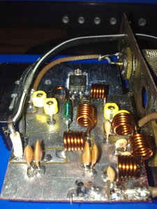 This fm rf amplifier uses 2SC1971 transistor to provide 5 watts of output. Output matching is adjusted via the two 40pF trimmer capacitors likewise also to the input. Note that the emitter of this transistor is directly grounded on the heat sink and should have a good thermal transfer. Driving power of 100 to 200mW can be applied in order to provide 5watts of output. Use a dummy load to tune this amplifier and remember that the transistor is biased in Class C, sufficient filtering should be followed after the output to minimize all the harmonics. Use ground plane construction technique in the PCB lay-out for best result, the more the grounding the better. If you have hard time finding the 10uH rf choke, try to wind 1/2 meter of 0.2mm enamel wire over a 33K 1/2 watt resistor and solder the coil ends to the legs of the resistor.
Posted on Monday, May 9, 2011 • Category: AVR
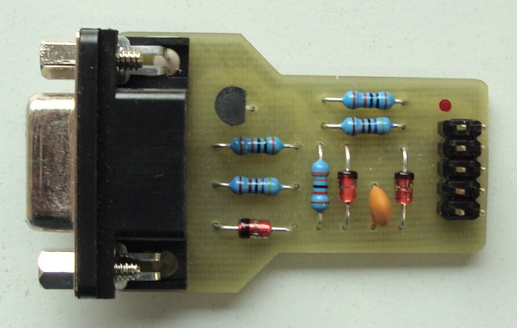 This is a very simple and easy to build programmer for Atmel microcontrollers from AVR family. The microcontrollers must support serial programming. This programmer is connected to a PC through the RS232 serial interface and can be used with the PonyProg or Avrdude software programmer. The programmer is quite simple and it is based on the SI-Prog from the author of PonyProg software. The Zener diodes D2, D3 with the resistors R2, R3 reduce the voltage from the ouput pins DTR, RTS on the serial port to around 5V which is suitable for microcontroller (MOSI, SCK). MISO signal is connected directly to the input CTS pin. The Zener diode D1 with the resistor R1 drive the NPN transistor T1, which controls RESET signal. The AVR microcontrollers are in reset when the signal has low level. The resistor R5 works as a pull-up for reset signal. The resistor R4 helps to close the transistor T1. The programmer has standard 10 pins header.
Posted on Monday, May 9, 2011 • Category: FM Transmitters
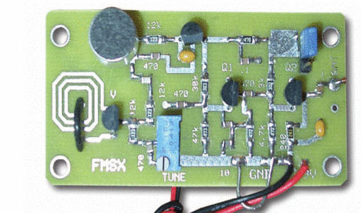 Presented here is a low-power FM transmitter with varactor diode tuning using surface-mount devices (SMD) that will be received with a standard FM radio. Soldering surface mounted devices is not so hard and actually is quite easy. There are many designs for small FM transmitters but they have some problems. First, you need an audio amplifier to get enough modulation. Second, the antenna is attached directly to the collector. Third, the coil L must be wound by hand and adjusted by stretching. It all ads with a weak signal that tends to drift in frequency. In contrast the transmitter schematic we present here eliminates some of those problems, using varactor diode for tuning and modulation, givin great sensitivity without an audio amplifier.
Posted on Sunday, May 8, 2011 • Category: FM Transmitters
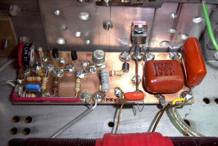 This particular transmitter was later shipped up to VY1JA in the Yukon where, thanks to Jay's excellent antenna system, it was heard in Europe as well as in New Zealand during one of the Trans-Pacific Tests! Running 24 volts on the final will produce 100 watts into a 50 ohm load.
The transmitter utilizes a 4060 binary counter IC chip as both the crystal oscillator and frequency divider. I used a 2200 kHz crystal along with the 'divide-by' sixteen output to produce a signal at 137.5 kHz. Other combinations of crystal frequencies and 'divide-by' combinations may also be used since the 4060 features divided outputs for f/32 (pin 5) and f/64 (pin 4), among others. You may have a 4MHz crystal or an 8MHz crystal in your junk box that will put you in the band using these output pins.
Posted on Sunday, May 8, 2011 • Category: Remote Control
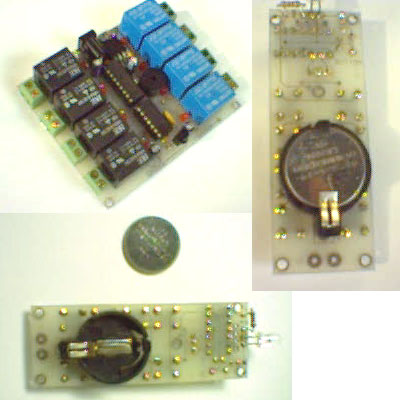 This IR remote control that you can use to control other devices or circuits up to 8 devices.
The control codes are sent in RC5 format modulated to about 38 kHz carrier frequency.The IR transmitter powered by the CR2016 which is a 3V button Cells Battery CR2016.To extend the life of the battery this is done by putting the CPU into SLEEP mode for most of the time and wake-up only when a key is pressed. PIC16F630 is the heart of the transmitter used to send IR command to receiver.It also generate 38KHz carrier frequency.The CR2016 is 3V battery which is supply for the circuit.
When any key not pressed the CPU work in SLEEP mode to reduce baterry power consumption and wake-up only when any key pressed. To wake-up the CPU from SLEEP mode the CPU use interrupt on change feature which interrupted when the state on PORTA change then the program execution after an interrupt is at the interrupt vector, if the global interrupt is not enabled, the program starts executing the first line of code right after the SLEEP instruction.In the interrupt service routine the software will scan the key that pressed and send IR command appropriate with key pressed.
Posted on Saturday, May 7, 2011 • Category: Remote Control
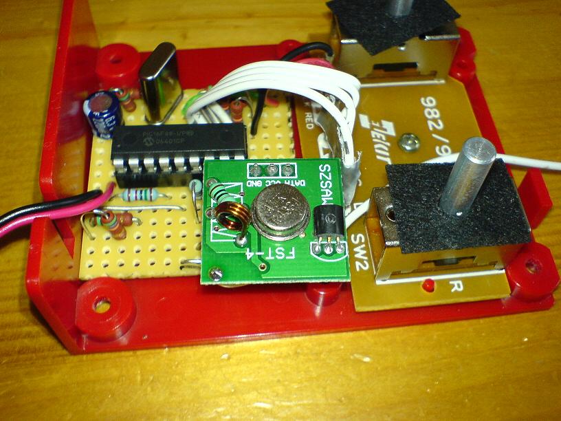 This is a 8 channel RF remote control project. The transmitter powered by 5V.the RF module I used had long start-up and power down period after receiving a high pulse. To counter all of this I kept the receiver in constant standby mode, but sending a information all the time. That way the noise is flooded out, and the receiver will always respond. I had been trying all sorts of error detection methods and different ways of encoding the bytes, when I just gave up. Since the link is so noisy I decided to cut out all of the error detection methods and just make it accept anything it receives, and see what happened from there. But what do you know, it worked!
Posted on Friday, May 6, 2011 • Category: Amplifiers
 Here's a 2x60W LM4780 Power Amplifier. LM3886 is very interested in our project was the first project, and were acclaimed. But the feedback we receive from you, from scratch, we knew we should make a complete device. One reason for that, but hard to find and the LM3886 integrated into the original cost of a fact to be taken into consideration. In this project, in which hosts two LM3886 LM4780 integrated with Integration, ie, making a complete amplifier. Advantageous LM4780 is an integrated, cost of both purchase price aşacağından sahtesinin made of forged-not-at least we do not see, but also would have received only two LM3886 price, or even more cheaply. We mean the complete amplifier, pre-amplifier, power amplifier and power supply hosts, ready for use, kutulayıp living room you can put the head in a corner of the device. If your hand if you have preamps or power amplifier, may be helpful in other projects.
Posted on Friday, May 6, 2011 • Category: LED
 This the circuit light led flashing ,with show of 10 LED. By use integrated number circuit CD4017 perform be Decade Counter/Divider with 10 Decoded Outputs. Which it is integrated digital circuit CMOS then use the power supply about 9VDC. For a signal input continue the circuit can produce general frequency may use IC NE555 all right.
Posted on Friday, May 6, 2011 • Category: Power Supplies
This is a DC power supply circuit using the LM317T voltage regulator IC, which is the IC of this type is very popular among electronics hobby. Parameter to regulate the output DC voltage carried by the LM317 circuit with a maximum current of 1A.
LM317 output voltage of this circuit is 6V DC, source from the stress out of the 12V CT AC transformer, and then converted to DC half-wave voltage by diodes D1-D2, and filtered by C1 capacitor. The transformer is used should be about 1-2A.
Output voltage of 6V DC power supply circuit is determined by the value of R1 and R2. Diodes D3-D4 on the LM317 voltage current circuit to protect poor return for LM317 circuit IC. As for the other capacitors C3-C4 is used to refine the output voltage, and complete power supply circuits.
Circuit-Zone.com © 2007-2026. All Rights Reserved.
|
|
|