Circuit-Zone.com - Electronic Projects
Posted on Thursday, November 28, 2019 • Category: Motor Controllers
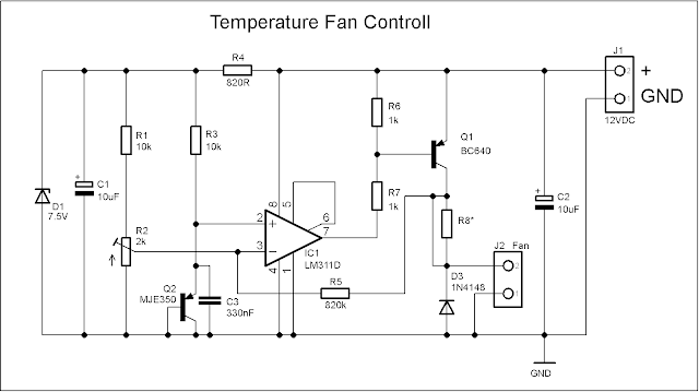
I published this schematic long ago in this article: Adjustable power supply and since then I made some improvements in PCB to make the board as small as possible. The idea is to be easy to attach the whole board to the heat sink which we want to monitor. The board is only 27mm x 27mm.
Posted on Monday, July 22, 2019 • Category: FM Transmitters
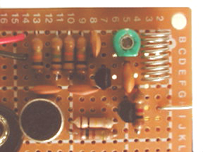 Learn to build your own mini FM transmitter. This fun project will show you how to build a mini broadcasting device that can transmit an audio signal up to a quarter mile to any FM receiver. It's easy to build and a good learning experience.
Posted on Tuesday, June 18, 2019 • Category: FM Transmitters
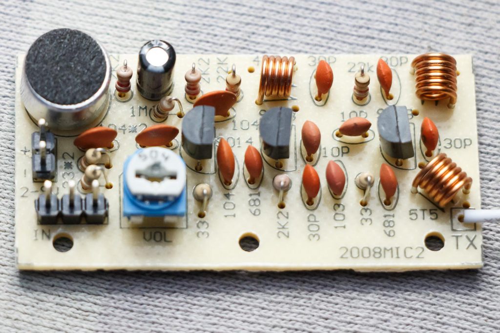 With this three stage transistor transmitter we can create and broadcast our mini radio station. We using S9018 transistor because it can handle very high frequencies, up to and including the VHF band. The first transistor on the left is a microphone audio amplifier for modulation. The gain can be adjusted with the potentiometer. The second transistor is the oscillator with a range of 80 to 103 MHz. The frequency can be changed with the upper coil 4T5 by pulling it slightly apart. The signal from the oscillator is very small, so that still needs to be amplified. The right most transistor is therefore an RF amplifier. This amplifies the signal from the oscillator to feed to the antenna. This transistor also immediately provides more stability, because the oscillator is not directly connected to the antenna.
Posted on Friday, June 14, 2019 • Category: Miscellaneous
 This is a simple arduino project for a soil moisture sensor that will light up a LED at a certain moisture level. It uses Arduino Duemilanove microcontroller board. Two wires placed in the soil pot form a variable resistor, whose resistance varies depending on soil moisture. This variable resistor is connected in a voltage divider configuration, and Arduino collects a voltage proportional to resistance between the 2 wires.
Posted on Tuesday, June 4, 2019 • Category: FM Transmitters
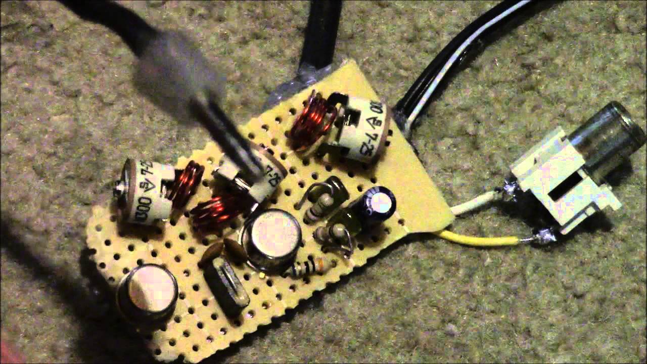 With a matching antenna, the FM transmitter circuit shown here can transmit signals up to 2 kilometers. The transistor Q1 and Q2 forms a classic high sensitive preamplifier stage. The audio signal to be transmitted is coupled to the base of Q1 through capacitor C2. R1, R3, R4, R6, R5 and R9 are the biasing resistors for the preamplifier stage comprising of Q1 and Q2. Transistor Q3 performs the collective job of oscillator, mixer and final power amplifier. C9 and L1 forms the tank circuit which is essential for creating oscillations. Inductor L2 couples the FM signal to the antenna.
Posted on Monday, April 15, 2019 • Category: Headphone Amplifiers
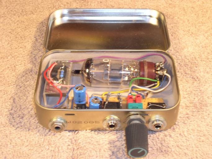 This little tube amplifier is easy to build and will fit into a small metal Altoids box and can be carried around. It can be build with few common parts, that should be readily available. Amplifier works with many tubes like 6DJ8, ECC88, 6922, 12AT7, 12AX7, DAF96, 1T4, etc. It is powered by 12V supply and power consumption may be optimized to allow for small rechargeable battery packs.
Posted on Monday, February 25, 2019 • Category: Power Supplies
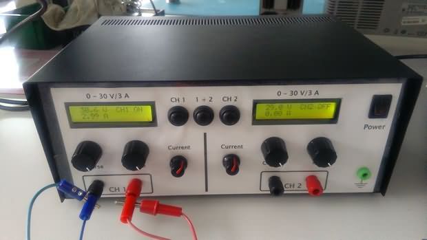 Presented here is a Laboratory Power Supply with 0-30V voltage and 0-3A current regulation. The schematic is pretty straightforward, it uses standard dual opamps such as TL082, TL062, TL072, NE5532, RC4558 and MC34072. The trimmer P3 adjusts the minimum current limit. P4 adjusts the maximum output voltage. After the final adjustment you may replace the trimmers with standard resistors. Power transistor dissipates quite a bit of heat and thus require a heatsink with optional fan. We may use two or tree transistors in parallel with emitter resistors to achieve more power. The transformer must be 100-120W with 27-30VAC output voltage.
Posted on Friday, February 1, 2019 • Category: FM Transmitters
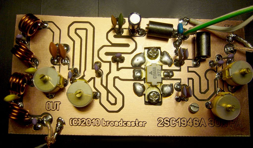 This RF Amplifier designed for FM broadcast using a single 2SC1946 VHF Power Transistor. This 10-30W RF amplifier circuit provides an appropriate power boost with an input of 1-3 watt. Tower are 30 meters high will send signal surrounding air should be around 15 km.
Posted on Tuesday, January 22, 2019 • Category: FM Transmitters
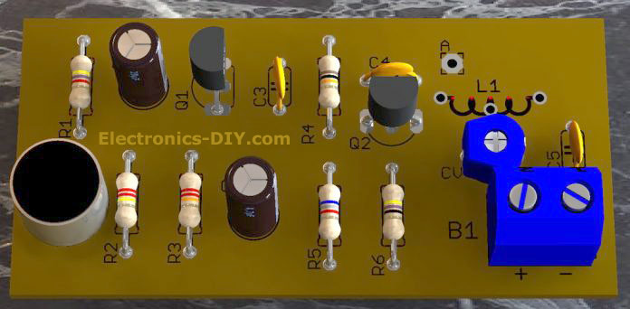 That small circuit transmitter it is ideal for ready espionage for strip from radio Fm or receiver of VHF. Of course the recreational purpose also exists and the children will adore to have a transmitter that allows to speak for a radio FM placed at distant place and like this pretend the secret agent.
Posted on Wednesday, November 14, 2018 • Category: FM Transmitters
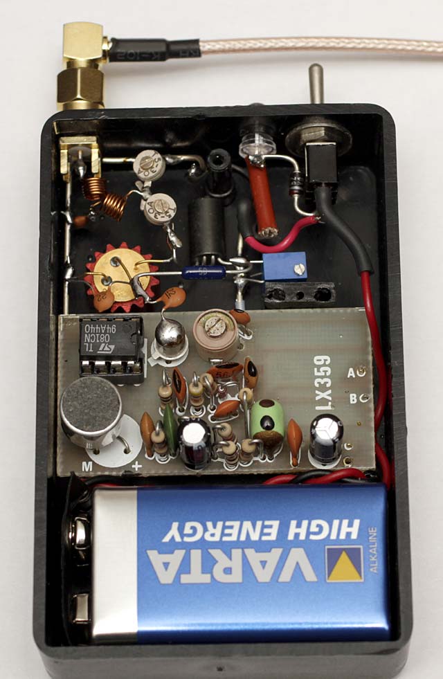 Powerful microtransmitter that can cover 3km range. To amplify the signal, a 2N3866A transistor is used that can provide up to 1W with gain > 10dB (24Volt). In our case the output power is about 100mW depending on the input power of 10mW and 9V battery power supply. The transistor Q1 must be mounted with a heatsink, the heatsink must have small dimensions (cylindrical) in order not to increase the parasitic capacitance. The trimmer R2 serves to adjust the bias of the transistor, start with the trimmer fully open and close by measuring the current absorbed by the 9V, in my case you get 100mW at the output with a current of 50mA not increase this value as you only increase the absorption by heating the transistor without increasing output power, because the input power is too low. Clearly the 9V battery will be able to provide 50mA only for a few hours, if necessary have greater autonomy should be used a larger battery, but it is no longer a bug but simply an FM transmitter.
Circuit-Zone.com © 2007-2026. All Rights Reserved.
|