This project shows how to build a simple AM radio transmitter based on 555 timer IC. The circuit parts are: the 555 timer IC, a NPN transistor three caps, three resistors and a potentiometer. The circuit is able to generate an amplitude modulation signal at 600Khz and you are able to receive it using a plain AM receiver. The range is about 30-40 feet.
Posted on Friday, March 15, 2013 • Category:
AM Radio
VHF FM Aircraft Receiver is a superregenative receiver developed for listening to FM transmitters but also tunes the aircraft band and the top portion of the FM broadcast band. Receives both AM and FM (107mHz to 135 MHz). You can use this receiver with the any FM transmitter. The receiver is amazingly simple using only one transistor for the receiver section and one IC for the audio section. This circuit is a self-quenching regenerative RF receiver also known as a superregenerative receiver. A superregenerative receiver performs two basic functions. First it feeds back a portion of the received signal from it’s output in phase to its input; and second a super audible quenching oscillator drives the amplifier through the point of oscillation and maximum sensitivity and then quenches the oscillation repeatedly. This keeps the feedback from driving the circuit into self-oscillation and allows the signal to be regenerated over and over again. In this version of the circuit, both functions are performed by the circuitry associated with Q1.
The rest of the circuit, shown to the right of L3 in the schematic, comprise the audio amplification circuit and are centered on the LM386 Audio Amp IC. In this configuration the LM386 is set at a gain of 200 and feeds it’s output to a standard 1/8-inch diameter stereo phone jack. The audio can then be heard by plugging any standard stereo headset into the jack.
Posted on Sunday, November 13, 2011 • Category:
AM Radio

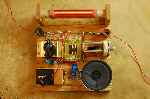
AM radio built around 555 timer chip. The only active device (silicon, germanium, or otherwise) is the LM555. The tuning is accomplished with an inductor and a capacitor, and the LM555 acts as an AM demodulator and class-D power amplifier to drive the speaker. You may be wondering how all this is accomplished with a 555. Here’s how the circuit works: The AM radio signal is tuned by inductor L, which is 300 turns of wire on a 1/2 inch diameter cardboard tube made out of a paper roll, along with the 100pF variable capacitor. One end of the parallel configuration of L and C connects to an antenna (surprisingly long!) and the other end connects to a ground wire which is tied to the AC outlet ground (old books tell you to ground it to a water pipe). So far this is exactly like an AM crystal radio.
The 555 timer is configured as a pulse width modulator in a non-traditional configuration. If I used the standard approach and connected the input to the CV pin, the low impedance of the pin would prevent the circuit from receiving any radio signals. I had to invert the circuit and tie both high impedance analog pins, Threshold and Trigger to the radio signal input. This is the reason why the CMOS version of the 555 timer performs much better than the standard bipolar, which has higher input bias current.
Circuit-Zone.com © 2007-2026. All Rights Reserved.