Circuit-Zone.com - Electronic Projects
Posted on Wednesday, December 29, 2010 • Category: iPOD Hacks
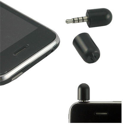
If you have ever wanted to plug in a pro-quality microphone and headphone to an iPhone or iPod touch, pay attention and read on. This guide will show you how to make a cable that will allow you to do just that. It’s not that hard as long as you can solder well, and can locate the right stuff. But in the end, you’ll end up making a little dongle that will allow you to plug in a mic and headphones separately.
Posted on Wednesday, December 29, 2010 • Category: Antennas
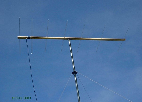 This simple 7 element Yagi is ideal for portable operation. The elements can be removed and replaced in a few minutes. The 2.42 Metre boom will fit inside my car. All of the elements are made from 6mm solid aluminum rod. The boom is made from 50x25mm (2x1 in) timber. The driven element is a half wavelength dipole. Unlike the more common type of folded dipole, this dipole is folded on one side but not on the other. For want of a better name, lets call it a 'half folded dipole'. The co-ax cable braid is connected to the centre of the dipole. The co-ax centre conductor is connected to the folded dipole section (see diagram above).
Posted on Monday, December 27, 2010 • Category: Miscellaneous
 Using the GPS Satellite system offers the advantage of very accurate timing and by extension, frequency control. The long term error is to all intents and purposes zero, with time and frequency accuracy being comparable to the international standard. The traditional route is to use a relatively low cost GPS receiver module which outputs a 1 Pulse per second signal (1 PPS) aligned to UTC. Basic GPS modules such as the Garmin GPS25 and Motorola Oncore have been around for some years and are available at low cost. It is possible to phase lock a divided down crystal oscillator to this 1 PPS signal and transfer its long term stability to , say, a 10MHz reference which is subsequently used for deriving any LO and beacon frequencies. The subsequent PLL system is usually described as a GPS Disciplined Oscillator rather than locked, since it is not, strictly speaking, actually ‘locked’ to the GPS system at all; just controlled by it via the 1 PPS generated by software in the receiver module.
Posted on Monday, December 27, 2010 • Category: Miscellaneous
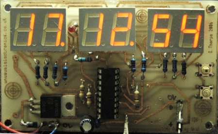 I decided to build a device to permanently display accurate time received from a cheap GPS module installed in my workshop.
Having obtained a PIC18F1320 microcontroller for experimentation, I wanted to learn about the new features of the PIC18F range using only minimal hardware to control the display.
I am currently using it with the on-chip 8Mhz oscillator only and driving a six digit led display, multiplexed with further saving of chip pins by a technique pioneered by Charlie Allen of Maxim-Dallas for their MAX6951 LED display drivers called “Charlieplexing” (see their application note AN1880).
I would have liked to have used a MAX6951 chip for better display brightness, but they appear to be only available in "Quarter Size Outline Packages" (QSOP) - the leads are very close together,not easy to experiment with.
Another alternative would be to use a MAX7219 display driver, this chip has a serial interface and an option to adjust the display brightness - something I may try later.
Posted on Monday, December 27, 2010 • Category: Miscellaneous
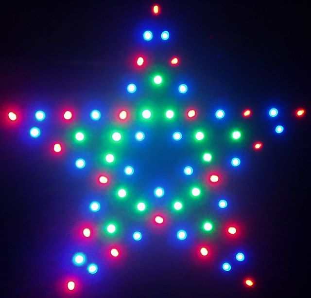 The star is about 35cm across and designed to be displayed indoors in a window.
I originally created the star three years ago using a 16F872 controller. The original version worked ok - but had no spare memory for adding more features.
This new version uses a 18F2620 because I now prefer the 18F series and decided it would be a good general purpose 28 pin chip to use. It has more than enough memory (64K) so I can add as many features as I want now.
(It should also work using a PIC18F2525 instead if you find it easier or cheaper to obtain)
Since, I made the first version, brighter LEDs are now available and cost is much lower - this project currently uses a total of 60 comprising of 25 Blue, 15 Green and 20 Red.
Posted on Friday, December 17, 2010 • Category: PIC
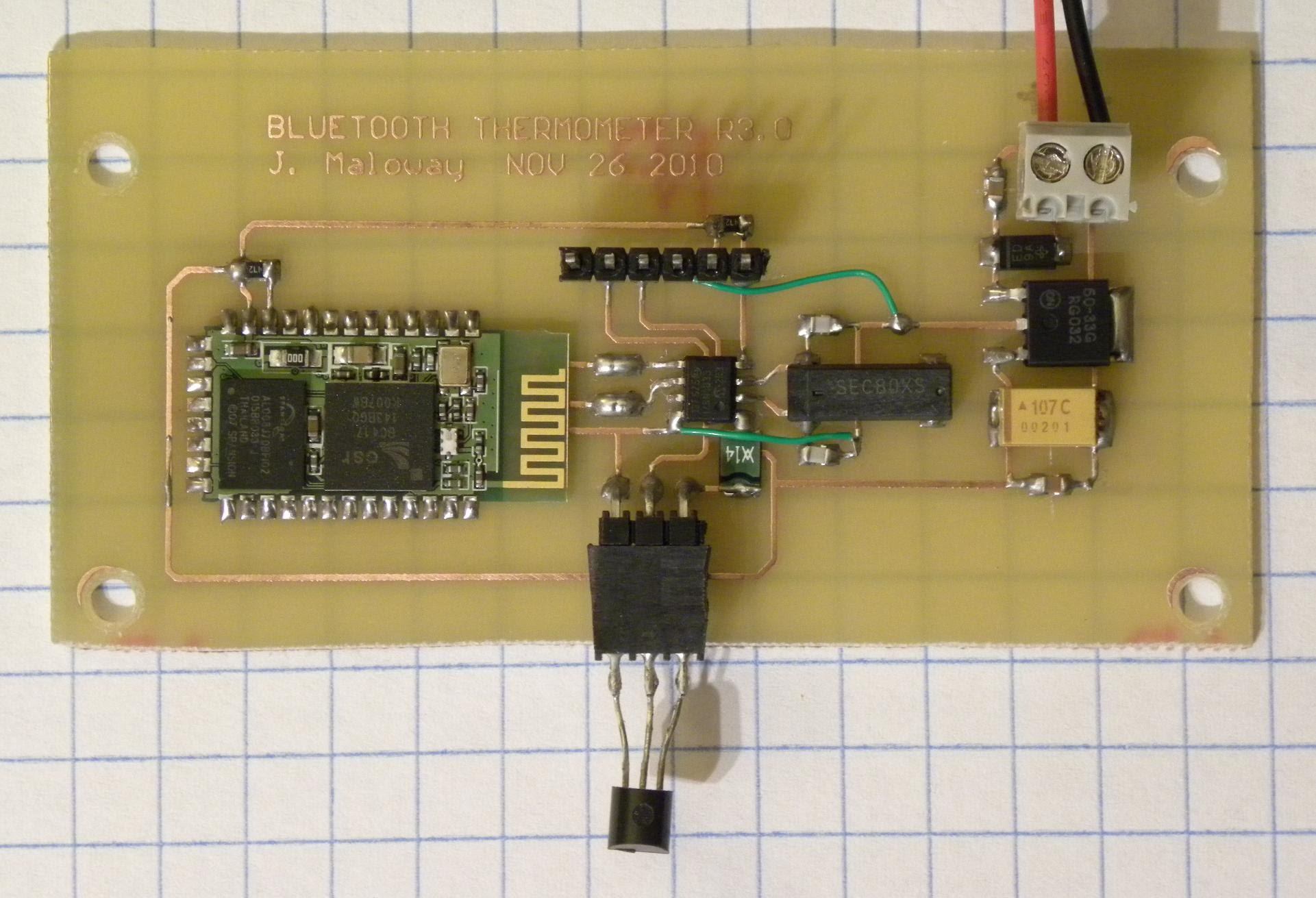 One morning I woke up and wanted to know what the temperature outside was, and instead of running over to Home Depot and picking up a $2.00 glass thermometer, I decided to build my own wireless temperature sensor. At the heart of the board is a PIC12F675 microcontroller in an SO8 package. The right-hand side of the board houses the linear power supply (LP2950), bottom-center is the DS18B20 1-Wire temperature sensor, and out in left-field you can see the Sure TTL Bluetooth Module.
Posted on Friday, December 17, 2010 • Category: Sensors
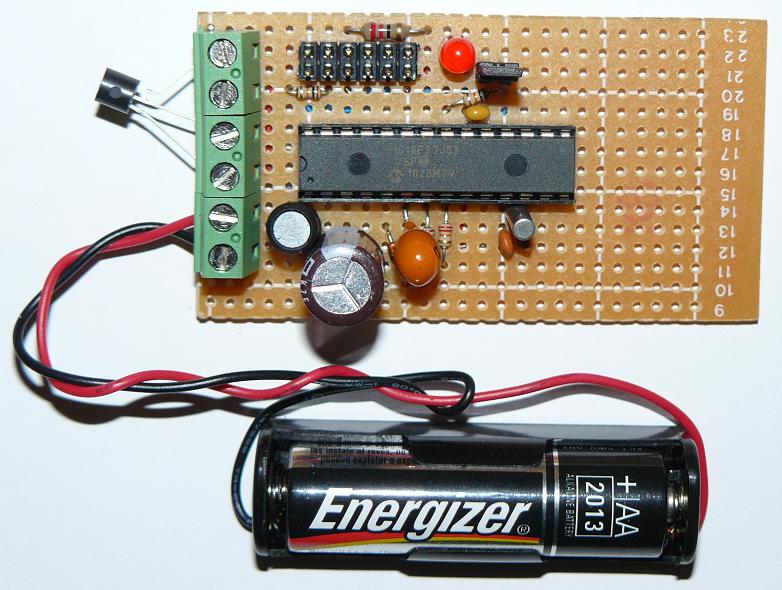 The MCP9700, MCP9700A, MCP9701 and MCP9701A Temperature Sensors from Microchip offer exceptional performance for the low price. Each have different temperature ratings and accuracy parameters. MCP9700, MCP9700A, MCP9701 and MCP9701A sensors are available in different packaging and are very simple to interface with. Vdd, GND and Vout are all that are required. You should check the datasheet to get a better idea of the parameters for the device you decide to use, though keep in mind that the user module listed below will automatically calculate the temperature depending on the device in use.
Posted on Wednesday, December 15, 2010 • Category: Miscellaneous
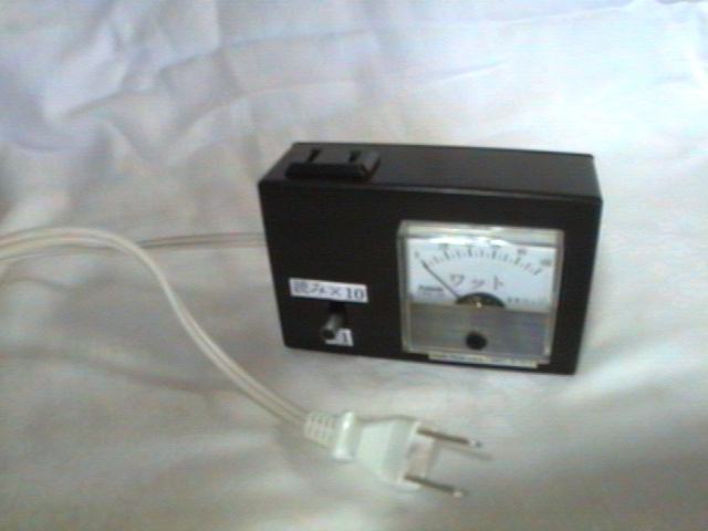 If you attempt to save power in the house thoroughly, you can not ignore the standby power consumption of appliances. We made a device to measure the power consumption of appliances. Actually, to say the AC power meters measure the 100V AC current is flowing in the power cord over do it. In general, the voltage is measured casually, is difficult to measure the current. To cut off a part of the circuit current flow from a current meter must be connected to it.
Posted on Wednesday, December 15, 2010 • Category: PIC
The new PIC18F2550 Project Board was designed as the development platform for student projects. The board platform is suitable for developing the microcontroller based instrumentation. Students may build the signal conditioning board, plugs it to PIC project board, develops the code and programs it with loader cable easily.
Posted on Wednesday, December 15, 2010 • Category: Video
Circuit Video Amplifier by transistor BC547 & BC557
Circuit-Zone.com © 2007-2026. All Rights Reserved.
|