Automatic battery charger automatically starts the charging procedure when battery voltage drops below a certain predefined value and stops after the voltage has risen above the maximum allowed value. Setup can't be easier, just connect two alligator clips to battery terminals and plug the device in mains. This way it can stay connected for months and the battery will never overcharge. This comes very very handy when you have a scooter or a real motorcycle that you don't drive during the winter time. Because we all know what happens to a battery when not used and especially during the winter.
Posted on Wednesday, July 13, 2011 • Category:
Power Supplies
There are many types of power supply. Most are designed to convert high voltage AC mains electricity to a suitable low voltage supply for electronics circuits and other devices. A power supply can by broken down into a series of blocks, each of which performs a particular function. Each of the blocks is described in more detail below:
Transformer - steps down high voltage AC mains to low voltage AC.
Rectifier - converts AC to DC, but the DC output is varying.
Smoothing - smooths the DC from varying greatly to a small ripple.
Regulator - eliminates ripple by setting DC output to a fixed voltage.
Posted on Wednesday, July 13, 2011 • Category:
Test and Measurement
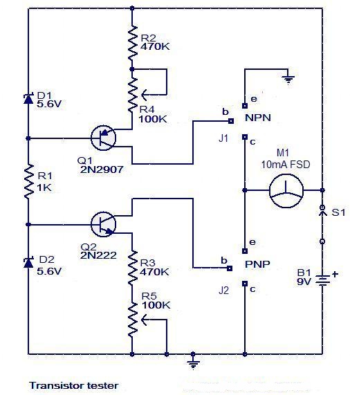
Here is a very simple circuit that can b e used to check the hfe of transistors. Both PNP and NPN transistors can be checked using this circuit. Hfe as high as 1000 can be measured by using this circuit.The circuit is based on two constant current sources build around transistors Q1 and Q2.The Q1 is a PNP transistor and the constant current flows in the emitter lead. The value of constant current can be given by the equation; (V D1 -0.6)/ (R2+R4).The POT R4 can be adjusted to get a constant current of 10uA.
Posted on Tuesday, July 12, 2011 • Category:
Power Supplies
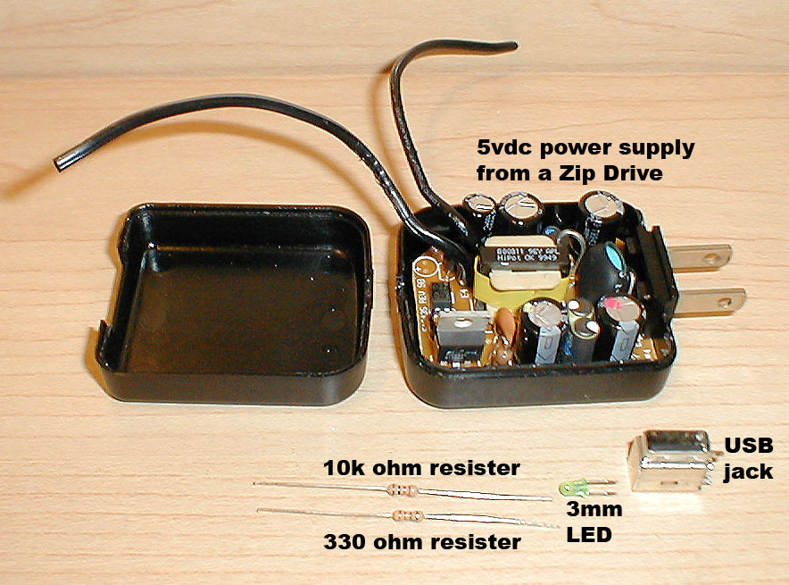
Here is a quick and easy way to make an USB charger / power supply powered by the wall outlet. This can be used to charge / power a PSP, iPod or any other USB device.
First you need to acquire a regulated 5 vdc wall wart rated at 500ma or higher. The one I used is from an IoMega Zip drive. It has a switching regulator with an output of 5vdc @ 1amp. This is a cool way of making an old wall-wart (plug in power supply) into a useful USB power supply and requires very few extra components.
Posted on Tuesday, July 12, 2011 • Category:
Sensors
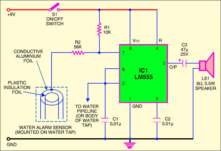
This is a simple water alarm. At the heart of this circuit is a small water sensor. For fabricating this water sensor, you need two foils—an aluminium foil and a plastic foil. You can assemble the sensor by rolling aluminium and plastic foils in the shape of a concentric cylinder. Connect one end of the insulated flexible wire on the aluminium foil and the other end to resistor R2. Now mount this sensor inside the water tap such that water can flow through it uninterrupted. To complete the circuit, connect another wire from the junction of pins 2 and 6 of IC1 to the water pipeline or the water tap itself.
Posted on Monday, July 11, 2011 • Category:
FM Transmitters
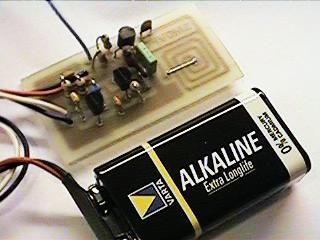
This Wireless Microphone FM Transmitter has been a very popular project with beginners and experienced constructors alike. It has been used inside guitars and as the basis of a remote control system. I do however, receive many requests for a higher powered circuit and better microphone sensitivity. Now I can introduce the new FM Wireless Microphone, which also has a better frequency stability, over 1Km range (under ideal conditions) and is good on microphone sensitivity. This has been achieved by adding an RF amplifier buffer (with 10dB gain) and an AF preamplifier to boost the modulation a little.
Posted on Monday, July 11, 2011 • Category:
Sensors
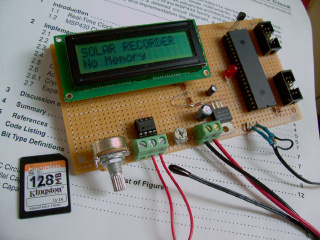
Build a simple data recorder for solar energy lab. The Recorder uses a calculator solar cell as the input sensor and a Multimedia Memory Card for nonvolatile data storage.
The device used for measuring daily insolation has been developed. The device was built with a PIC18F458 and the 128MB Multimedia Memory Card, MMC. The solar radiation is measured by a calculator solar cell. The PIC chip interfaces the MMC using SPI mode. The interval between samples is set to one minute. The firmware detects the memory card, assigns the file name and begins recording automatically. The LCD displays the file name, current sample and real-time ADC data. With the MMC flash technology and a cheap media card reader, the devices will be able to record huge amount of data and quick data uploading to the PC.
Posted on Saturday, July 9, 2011 • Category:
AVR
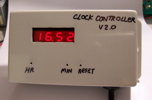
Build a digital clock that turns AC load on/off through relay with preset time. The clock is based around 7-segment LED display with multiplex connection and AT89C2051 microcontroller. It is nice to be used as the display for clock controller. So I spent my weekend built the board. Below are the pictures for outlook and internal. The board is quite small. The output has small relay for 0.5A AC load. The program clock.c was written in ‘C’ language and was complied by Micro-C Compiler from DunfiledDevelopment Systems. The memory model is TINY. The hex file of clock.c suitable for downloading by Easy-Downloaderis clock.hex.
Posted on Saturday, July 9, 2011 • Category:
Phone Circuits
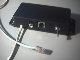
I needed a way to extract audio from a phone line for my DTMF decoder. I found a site full of examples on how to do it, and I built an interface that suited my needs:
RCA output, with a signal strong enough to be fed directly to an audio amplifier or line-in.
The interface can stay connected on the line at anytime (no problems with the ring signal), and does not take of the hook.
The interface must provide isolation from the line.
I discovered that it can also be used to inject audio in the line.
Posted on Saturday, July 9, 2011 • Category:
PC Circuits
PC LED Load is a device and software designed to display many shades of colors from green to red on your computer case LED. Colors are controlled completely by software and can be updated in real-time.
The PC LED Load circuit board is connected to one of the internal USB ports found on most newer motherboards. The only actual case modification required is in replacing the two (or more) front panel LEDs with tri-color versions. These are then connected to the PC LED Load circuit board.
Circuit-Zone.com © 2007-2026. All Rights Reserved.