Circuit-Zone.com - Electronic Projects
Posted on Sunday, June 1, 2014 • Category: Miscellaneous
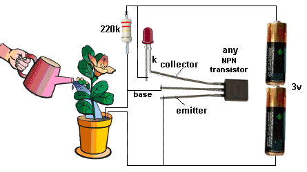
This simple plant water alarm circuit indicates when the soil is dry and the plant needs watering. The circuit does not have a current-limiting resistor because the base resistor is very high and the current through the transistor is only 2mA. Replacing 220K resistor with 1M potentiometer will provide adjustment when the alarm should be triggered depending on the moisture left in the soil.
Posted on Friday, May 16, 2014 • Category: FM Transmitters
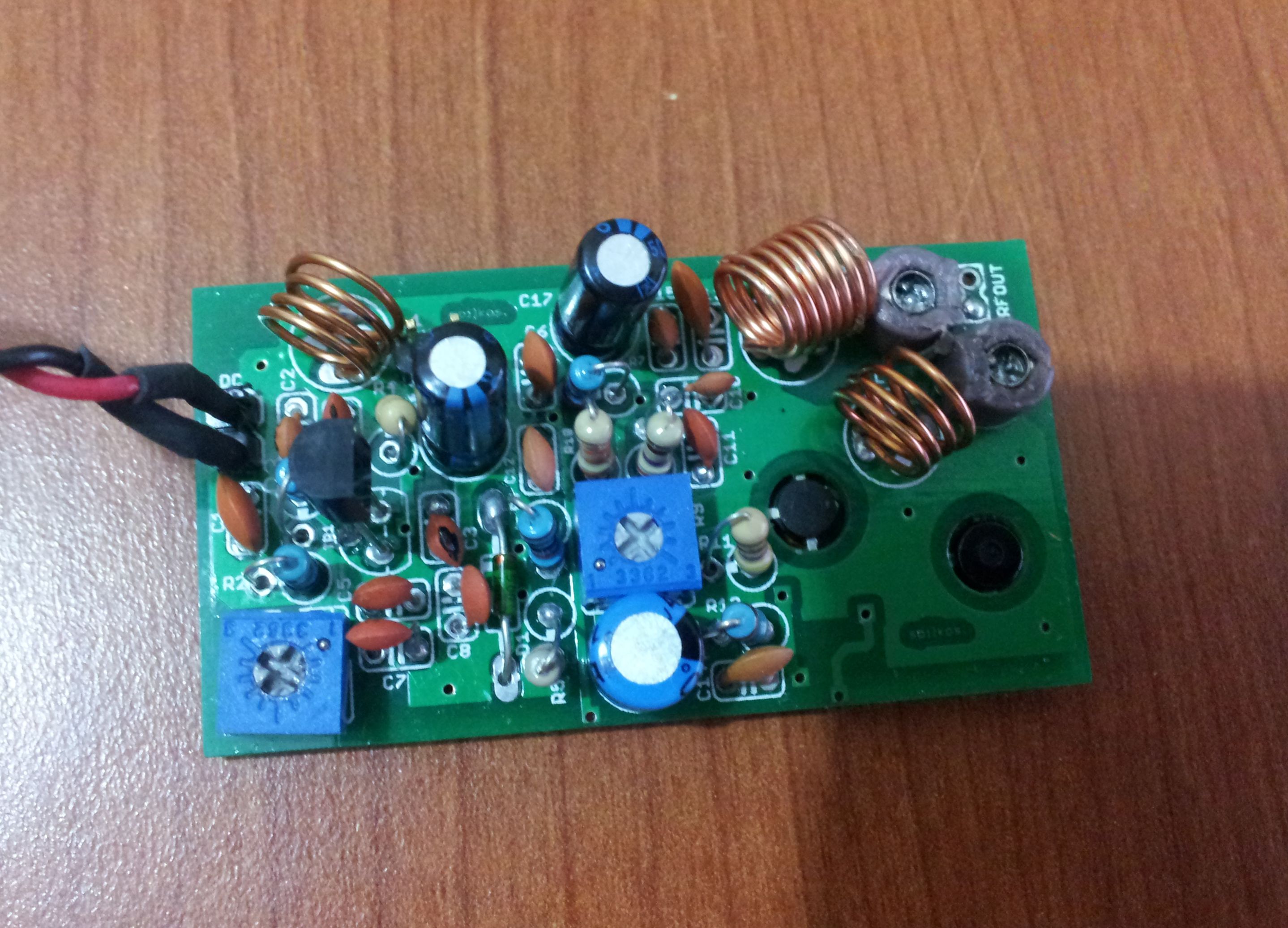 This is a VCO FM Transmitter. With good antenna (dipole placed outdoor and high) the transmitter has very good coverage range about 500 meters, the maximal coverage range is up to 4 km. To calibrate for maximum power connect 6 V / 0,1 light bulb to the output and use R1 to tune the right frequency, adjust L1 coil if necesary. Then use C14 and C15 to adjust the highest power (the highest light of the bulb). Then you can connect antenna and audio signal. Adjust R2 until the audio sounds as loud as the other stations.
Posted on Thursday, May 15, 2014 • Category: FM Transmitters
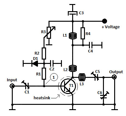 This is a 1 Watt FM Transmitter amplifier with a good design that can be used to amplify a RF signal in the 88 – 108 MHz band. It is very sensitive if you use good RF power amplifier transistors, trimmers and coils. It has a power amplification factor of 9 to 12 dB (9 to 15 times). At an input power of 0.1W the output will be 1W. You must choose T1 transistor depending on applied voltage. If you have a 12V power supply then use transistors like: 2N4427, KT920A, KT934A, KT904, BLX65, 2SC1970, BLY87. At 18 to 24V power supply you must use transistors like: 2N3866, 2N3553, KT922A, BLY91, BLX92A. You may use 2N2219 at 12V but you will get an output power of 0.4W maximum.
Posted on Tuesday, May 13, 2014 • Category: Miscellaneous
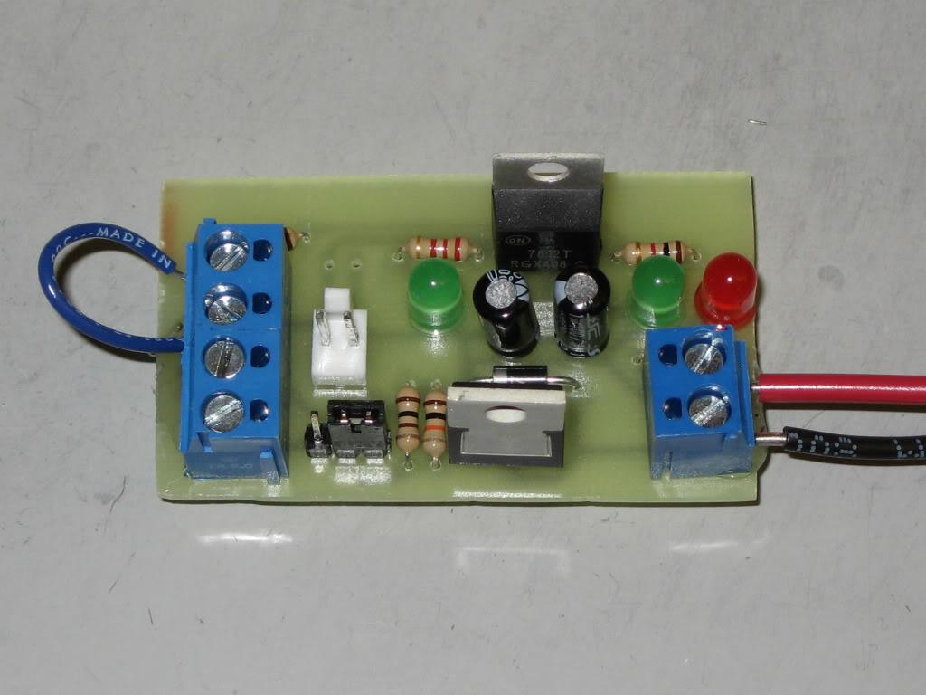 Constructing a MOSFET switch is one of the basic level electronics projects and could be useful for beginners to get a hang of the various FET transistors. The aim of this project is to make control a heavy duty DC load by constructing a simple switch. MOSFET transistors are capable of handling a large voltage and current. It is because of this feature that it is being much sought after for connecting heavy loads to a circuit or a microcontroller.
Posted on Friday, April 25, 2014 • Category: AM Radio
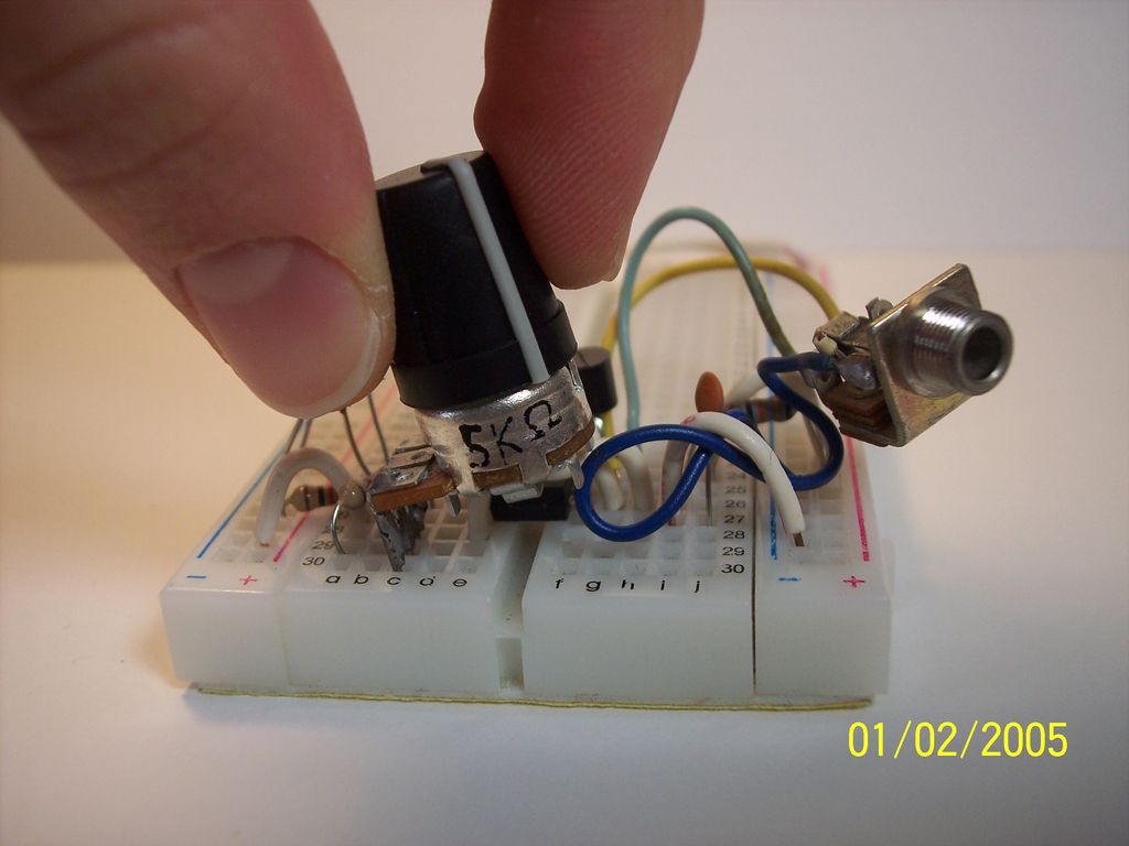 This project shows how to build a simple AM radio transmitter based on 555 timer IC. The circuit parts are: the 555 timer IC, a NPN transistor three caps, three resistors and a potentiometer. The circuit is able to generate an amplitude modulation signal at 600Khz and you are able to receive it using a plain AM receiver. The range is about 30-40 feet.
Posted on Tuesday, April 22, 2014 • Category: Power Supplies
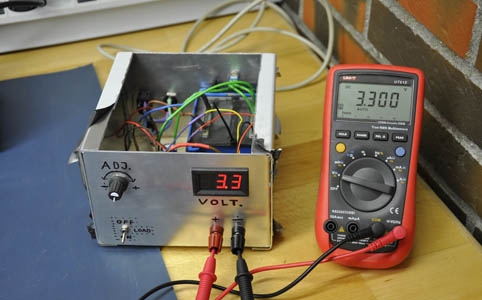 If you are starting to learn electronics variable bench power supply is the first thing you should build to power your projects. This simple power supply is built around the LM317/LM338/LM350 linear voltage regulator. The LM317 is one of the most popular voltage regulators on the market, and for good reason. It is very simple to use and requires very few external components. LM317/LM338/LM350 regulators provide a stable and reliable output voltage adjustable between 1.25V and 37V. The short circuit protection is also built right in the voltage regulator.
Posted on Monday, April 14, 2014 • Category: Arduino
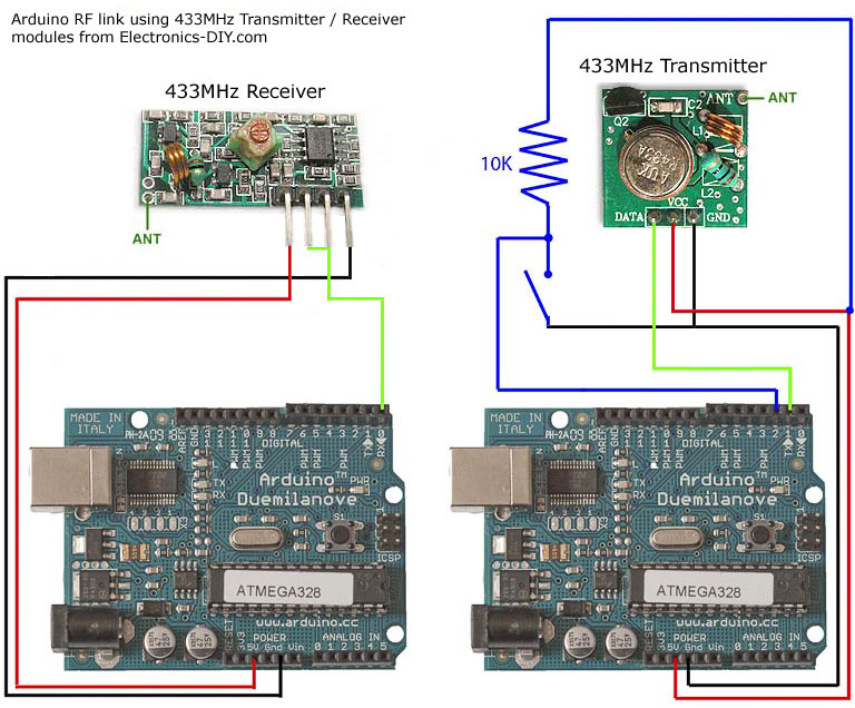 If you are looking into wireless communication between two Arduino modules, this project might be helpful. It uses low costs RF transmitter and receiver from Electronics-DIY.com to establish radio link between two Arduino boards up to 500 ft. Data can be transferred serially at the maximum rate of 2400 bps. The schematic shows how receiver and transmitter is hooked up to two different Arduino boards. When wiring the receiver / transmitter you only need to give them power / ground and then a pin for the TX (serial transmit) or RX (serial receive) pin. I also wired a button to the Arduino doing the transmitting, and used the LED on pin 13 that is built into my Arduino boards on the receiver so I could test this setup. The test app just flashes LED on the receiving board when a button is pressed on the transmitting board.
Posted on Tuesday, April 1, 2014 • Category: Frequency Wave Generators
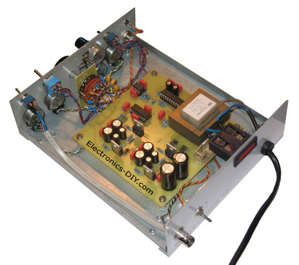 This is simple MAX038 generator. It produces sine, triangle and square waves from 1Hz up to 22MHz. The Amplitude, offset and duty cycle are adjustable to offer wide range of generated signals.
Frequency adjustment is made as a rotary switch S8 with a capacitor bank and variable resistor P7. Amplitude, offset and duty-cycle are performed via variable resistors. Switch S5 selects generated waveform.
Posted on Sunday, March 9, 2014 • Category: Test and Measurement
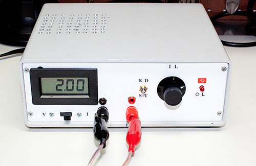 An adjustable power load is a piece of test equipment that often comes handy in the development of a certain electronics projects. For example, when you are building a power supply, it will come a time when you need to "simulate" a load to see how well your design performs as the load varies. Adding power resistors to the output can sometimes do in a pinch, but often you will not have the right resistor value handy with the right power rating for the test. This is where an adjustable electronic load comes handy. In this article, I'll show how you can build one using common components available to the electronics hobbyist.
Posted on Thursday, February 27, 2014 • Category: Amplifiers
LM3886 is a high-fidelity audio power amplifier IC capable of delivering 68W of continuous power using 4 Ohm speakers. LM3886 provides excellent S/N ratio of 92dB and above as well as extremely low total harmonic distortion over the audio spectrum.
LM3886 comes equipped with Self Peak Instantaneous Temperature Protection Circuitry (SPiKE) that makes it a class above other discrete and hybrid amplifiers. SPiKe Protection makes LM3886 amplifier safe against problems like over voltage, under voltage, overloads, shorts to the supplies, thermal runaway, and temperature peaks.
Circuit-Zone.com © 2007-2026. All Rights Reserved.
|