Circuit-Zone.com - Electronic Projects
Posted on Tuesday, March 20, 2012 • Category: FM Transmitters
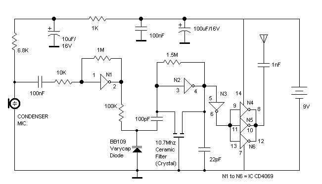
The RF oscillator using the inverter N2 and 10.7Mhz ceramic filter is driving the parallel combination of N4 to N6 through N3.Since these inverters are in parallel the output impedance will be low so that it can directly drive an aerial of 1/4th wavelength. Since the output of N4-N6 is square wave there will be a lot of harmonics in it. The 9th harmonics of 10.7Mhz (96.3Mhz) will hence be at the center of the FM band. N1 is working as an audio amplifier. The audio signals from the microphone are amplified and fed to the varicap diode. The signal varies the capacitance of the varicap and hence varies the oscillator frequency which produce Frequency Modulation.
Posted on Monday, February 20, 2012 • Category: Power Supplies
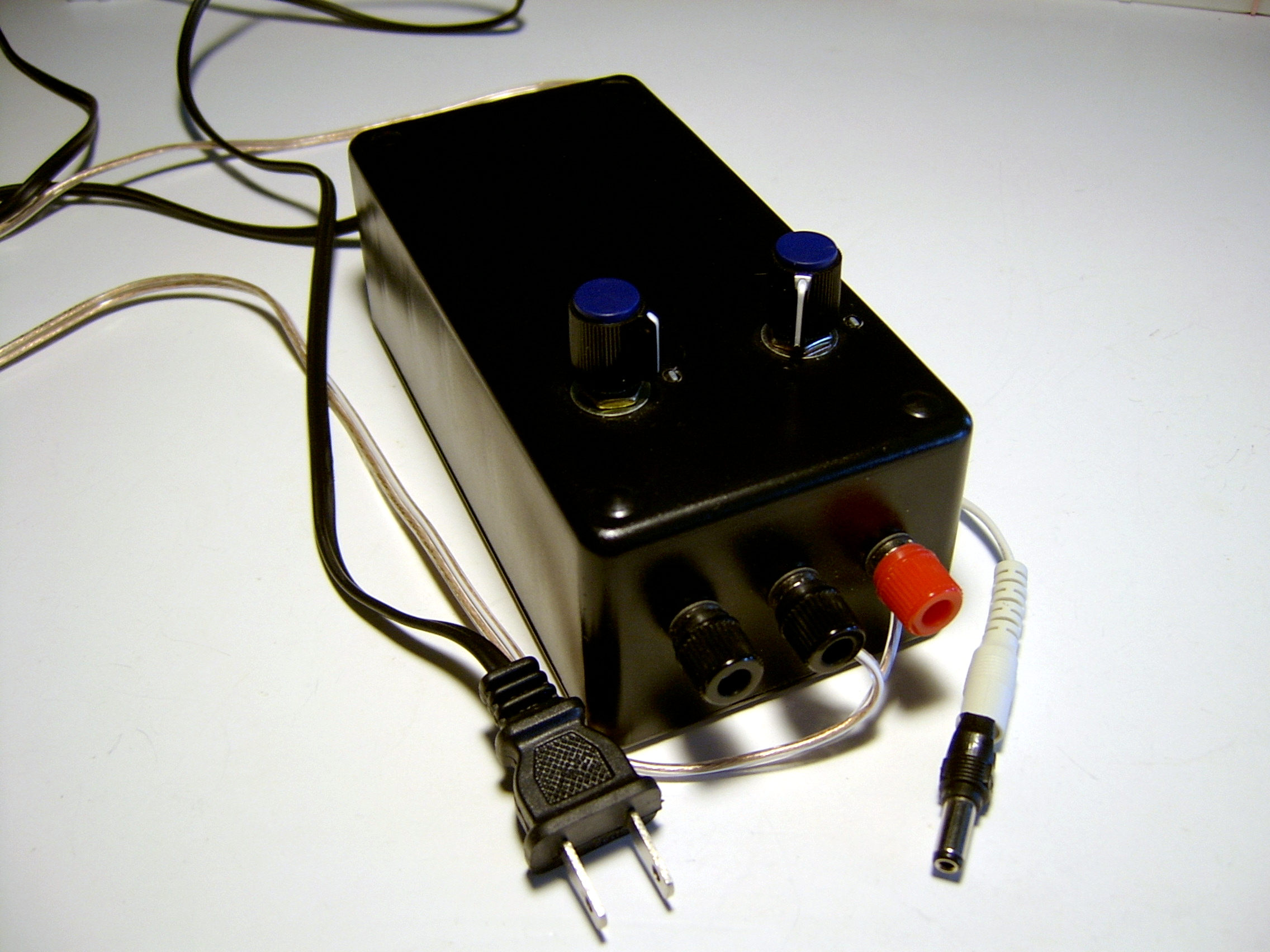 Split power supply provides a stable regulated bipolar voltage in the range ±1.5V to ±17V. It is based on LM317/LM337 linear voltage regulators that also have a short circuit protection. Most parts are easily accessible, including a 6"x3"x2" project box, 12V 1.2A center tap transformer, pots, knobs, etc. Power supply schematic shows how to wire LM317/LM337 to get +/- split voltage output.
Posted on Wednesday, February 15, 2012 • Category: FM Transmitters
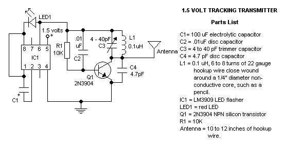 With this circuit you can build a very small tracking transmitter that can be tracked using a FM broadcast band radio receiver. The transmitter can be powered from any 1.5V volt battery or power supply. Transmitter has a range up to 1 mile depending on battery voltage, height above ground, receiver sensitivity, and antenna length. Under certain conditions distances of 1 mile have been achieved. It is recommended that this transmitter be used with FM radios that can tune continuously across the dial. The better the receiver and receiver antenna system the greater the practical range of the transmitter, however good functionality can be achieved with the least expensive radios and using only the standard telescoping antenna included with most radios.
Posted on Tuesday, February 14, 2012 • Category: Battery Chargers
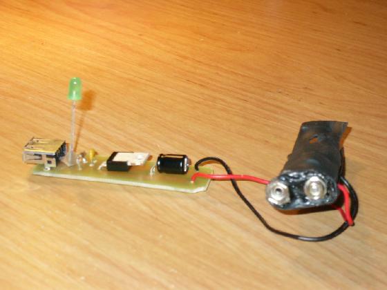 Portable USB Charger is a device that will charge things like Ipods, PDAs, that accepts charge from a USB port. It runs off a 9-V battery, and through the simple circuit, out comes a regulated 5-V perfect for a USB port. Portable USB chargers will always be handy, lets face it these days every gadget around us has USB charging capabilities. This is a very basic and simple project, and cheap too. Maybe its time for you to build your own diy portable USB charger.
Posted on Tuesday, February 7, 2012 • Category: FM Transmitters
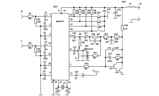 Here's BH1417 USB FM Transmitter with built-in PLL circuit. Its low-frequency signal is converted into high-frequency, which can take any audio device with FM radio (stereo, car CD, MP3, DVD player, etc.), as a normal radio station. Transmitter power is sufficient for reliable reception of its signal within a few tens of meters. The basis of the device is a chip BH1417F, included in a typical scheme. This device contains all the necessary circuitry to generate a composite stereo signal c of the pilot tone, the RF generator with PLL and power amplifier. A detailed description is given in.
Posted on Wednesday, February 1, 2012 • Category: FM Transmitters
 Here's a long range 300mW FM Transmitter for the 88MHz to 108MHz band. This particular TX is of special interest to those wishing to build low power Power Amplifiers for the VHF bands since it used impedance matching, power amplifier and antenna filtering, all of which should be used by radio constructors, whether it be for amateur radio or any other form of radio. The features of this project are: Higher output power - 150mW min (at 9v) and 300mW+ (at 12.5v). Very pure output signal due to careful design and filtering. VARICAP modulation - possibility to add a synthesizer. Single sided Printed Circuit Board, only 40mm x 72mm. Covers the domestic FM band - 88MHz to 108MHz. Easy to build, but coil winding experience IS required
Posted on Tuesday, January 24, 2012 • Category: LED
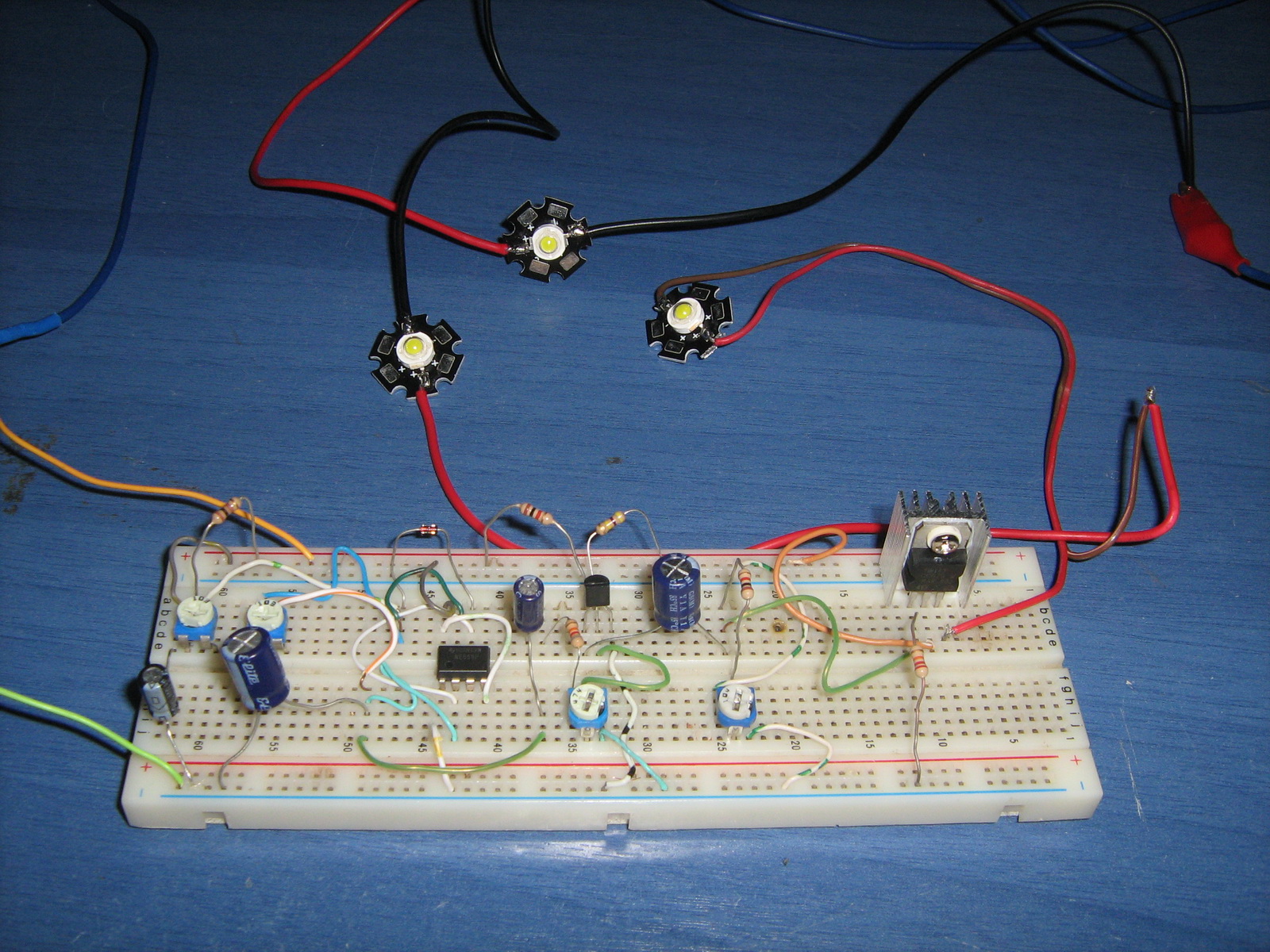 Here is a circuit for simulating breathing / pulsing LED with the 555 timer chip. It became very popular and i received many comments and emails with people that made this circuit and worked fine, as well as comments with people that had troubles converting it to operate at 12 volts supply. It was designed to operate with 5 volts, because i plan to use it for a future PC mod. Since the PC power supply has 5 volts output, and since the LEDs that i plan to use require 3.8 volts to operate, choosing 5 volts for supply was the best choice to minimize power dissipation on the transistor.
Posted on Tuesday, January 17, 2012 • Category: FM Transmitters
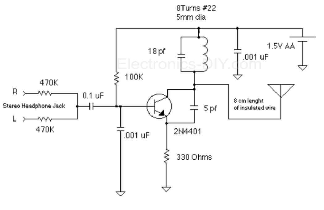 The objective of this 1.5V FM Broadcast Transmitter design is to provide a simple low-power transmitter solution for broadcasting audio from various audio sources. This transmitter accepts stereo input via two 470K resistors. Since there is no audio level control on the input, the audio level out from the source needs to be adjusted. Or, you can just add a 10k as an input level control. Transmitter's frequency, as built is tunable via spreading or compressing the coil to the desired frequency, and the coil can be glued down. If you want to make one that's tunable, it might be easiest to reduce the 18 pf capacitor and put a small trimmer capacitor in parallel with the inductor (across the reduced value capacitor). Voltage variable capacitors would be an nice alternative to a mechanical variable capacitor but they don't offer much tuning range with only a 1.5V power supply.
Posted on Sunday, January 8, 2012 • Category: FM Transmitters
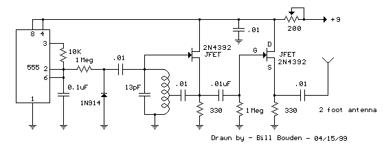 This FM Broadcast Transmitter circuit will transmit a continuous audio tone on the FM broadcast band (88-108 MHz) which could used for remote control or security purposes. Circuit draws about 30 mA from a 6-9 volt battery and can be received to about 100 yards. A 555 timer is used to produce the tone (about 600 Hz) which frequency modulates a Hartley oscillator. A second JFET transistor buffer stage is used to isolate the oscillator from the antenna so that the antenna position and length has less effect on the frequency. Fine frequency adjustment can be made by adjusting the 200 ohm resistor in series with the battery. Oscillator frequency is set by a 5 turn tapped inductor and 13 pF capacitor.
Posted on Wednesday, January 4, 2012 • Category: TV Transmitters
This is a small TV transmitter circuit which transmits in VHF band, negative sound modulation and PAL video modulation. It is suitable in countries where the B and G system is used.
Circuit-Zone.com © 2007-2026. All Rights Reserved.
|