Circuit-Zone.com - Electronic Projects
Posted on Thursday, April 21, 2011 • Category: Headphone Amplifiers
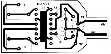
This audio amplifier uses TDA7053 which is an integrated class-B stereo power amplifier in a 16-lead dual-in-line (DIL) plastic package. Which requires minimal amount of external parts. This might be good solution to all of those who have PC with integrated sound card into motherboard. The main problem is that outputs of such sound cards are for active acoustic systems, this means that speakers must have power amplifier built in. If you decide to connect a headphones sometimes it might be not enough to provide required sound level.
Posted on Thursday, April 21, 2011 • Category: AVR
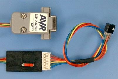 This is an AVR ISP Programmer which is controlled via COM port. Signal levels of the RS-232C line is converted to the target level, so that target device can operate in entire range of the VCC. And also it can be used as an communication cable to communicate between host PC and target program (this is explained in the following section). This ISP adapter is sufficient to develop most of the AVR applications.
Posted on Wednesday, April 20, 2011 • Category: Amplifiers
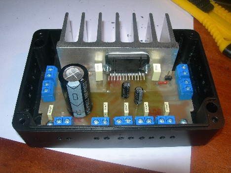 So this time I decided to make pretty simple but powerful enough car audio amplifier. For this I’ve chosen quad bridge car audio amplifier TDA7384 which has four input and four output channels with power capability of 4x35W. As datasheets of TDA7384 says it is low distortion, low output noise, low external component count. Also has Stand-By function and Mute function. It has several protections like from output short circuit to GND or to Vs, capable to handle very inductive loads, thermal limiter, load dump voltage. TDA7384 is an AB power amplifier cased in flexiwatt25 (eagle library is included in project archive) package witch is designed for high end car radio applications. It allows rail to rail output voltage swing with no need of boot-strap capacitors.
Posted on Wednesday, April 20, 2011 • Category: Oscilloscopes
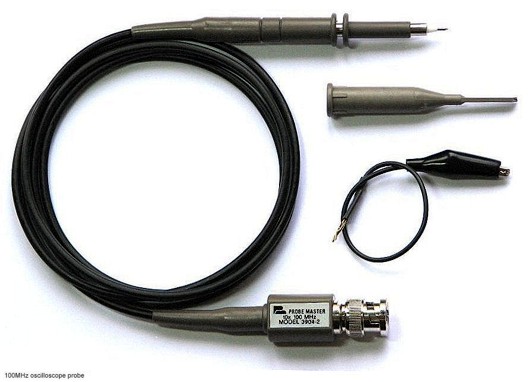 On the following article learn about Oscilloscope probes, their basic characteristics and proper calibration. Measuring signals with oscilloscopes may be challenging task especially high frequency ones. Without proper oscilloscope probes correct measurement of high speed time domain signals wouldn’t be possible. For high speed measurement you should consider signal parameters like amplitude, source impedance, rise time and bandwidth.
Posted on Tuesday, April 19, 2011 • Category: Sensors
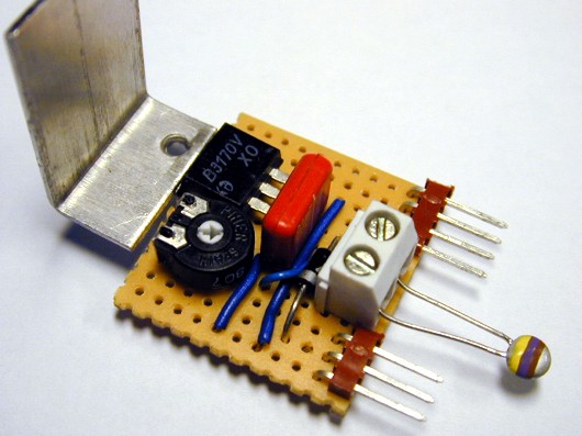 With this simple circuit you will be able to control the speed of a DC fan according to temperature measured by a temp sensor. It’s an ideal add-on for your PC cooling fans to eliminate produced noise. Requested by some correspondents, this simple design allows an accurate speed control of 12V dc fan motors, proportional to temperature.
A n.t.c. Thermistor (R1) is used as temperature sensor, driving two directly coupled complementary transistors wired in a dc feedback circuit.
An optional circuitry was added to remotely monitor fan operation and to allow some sort of rough speed indication by means of the increasing brightness of a LED.
Posted on Monday, April 18, 2011 • Category: Amplifiers
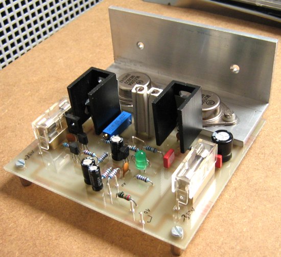 I am a big fan of surround sound. Up until the moment I finished this amp, I was using two two-channel amplifiers to power four speakers. This was very annoying, because it meant I had two volume controls. This invariably meant that the balance between front and rear was off. Added to this, was that the amplifier for the rear speakers was not very good. It produced too much noise, and allowed clicks and pops from the power grid through, to be amplified and heard. I decided I was going to build a four channel power amplifier, and later a pre-amplifier to feed it. You might wonder why I didn't choose to make a five channel one instead. This is because I don't see the use of the center channel. I will probably write an article detailing why, but for now, suffice it to say that four channels is enough for 2 dimensional sound, which is what 5.1 is as well.
Posted on Sunday, April 17, 2011 • Category: FM Transmitters
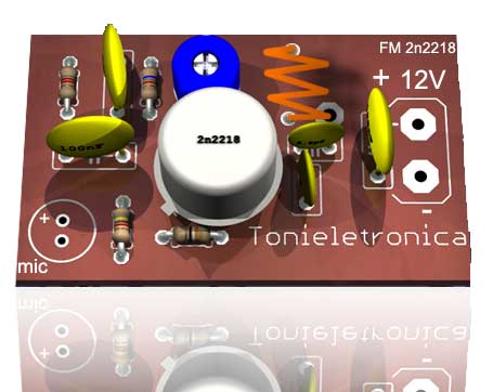 This small power FM transmitter can transmit more than 1 km in good conditions. The modulation can be made so much with a microphone or audio source. Circuit of power fm transmitter is built around 2n2218 transistor. Transmitter coil is 5 turns of enameled 22 AWG wire, with diameter of 1 cm without nucleus. Look at the capacitors that it should be ceramic. The antenna should possess from 15 to 40 cm. For transmission it ties a receiver of FM (radio) in the proximity to half volume in a free frequency (that there is not any radio operating), with a wood or plastic key, rotate the screw of CV to capture the frequency of the transmitter.
Posted on Saturday, April 16, 2011 • Category: Miscellaneous
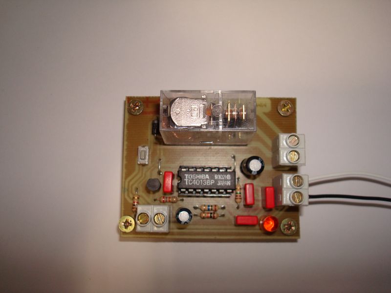 Small circuit, with which we can use to get rid of the standard switch and operate any type of load with a push of a tactile button. Voltage between 5 and 18 V DC ( depends on the operating voltage of the relay coil ) in terminal CN1. Output Current is 10A ( depends on relay contacts ) in terminal CN3 activated by external positive pulse or short-circuiting the terminal CN2. Circuit is protected against double pulses and rebounds.
Posted on Friday, April 15, 2011 • Category: FM Transmitters
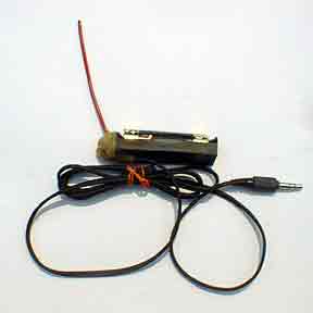 This implementation is adapted to rebroadcast the output of a CD player, television receiver, or radio receiver. I use it so that I can move about the house and listen to my favorite programs without disturbing others. Within and the house, I find that I can get 10 to 20 meters away from the transmitter with the small pocket FM receiver I carry in my shirt pocket. Your mileage may vary. The transmitter as built and pictured below (the transmitter is in the blob of hot melt glue on the end of the battery holder) does not have an on-off switch. I put a 1.5 AA cell that was run down too far to run my CD player in this transmitter and it ran for over a month before I replaced it. The one in the transmitter at this moment has been running it continuously for over three months. Current draw is only about a milliamp with a new battery (assuming you don't have a super-high beta transistor in which case the theoretical limit is about 2.5 ma). An on-off swich is not necessary, though it may satisfy an emotional need.
Posted on Thursday, April 14, 2011 • Category: FM Transmitters
9 Volt battery operated simple Mini FM Transmitter. FM Transmitter is very simple, compact, and has transmission signal with a range of 100-150m, good sensitivity and low current consumption. Transmitter's schematic consists of a bass amplifier for the first transistor and the proper frequency generator in the second. FM Transmitter divided transitional capacitor that allows you to set up a cascade separately.
Circuit-Zone.com © 2007-2026. All Rights Reserved.
|
|
|