Circuit-Zone.com - Electronic Projects
Posted on Saturday, June 5, 2010 • Category: Antennas
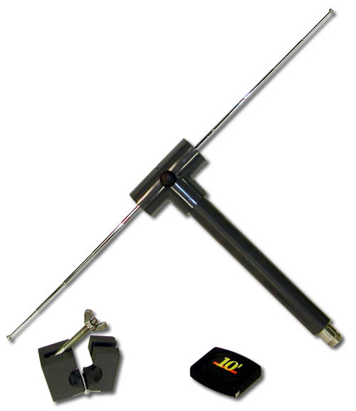
It is very easy to create a simple 1/2 wave dipole, all you need is some lengths of wire such as the core of some mains flex or even a straightened out metal coat hanger, some co-ax cable and a connector for your scanners antenna input (usually BNC or SMA).
Dipole Antenna
The formula to calculate the length of the antenna is 147/frequency in MHz, this give the total length of the dipole in centimeters. For example, to make a 150MHz dipole: 147/150 = 98cm so each element of the dipole should be 49cm
Posted on Saturday, June 5, 2010 • Category: Antennas
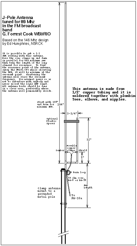 Tuned for 89MHz in the FM broadcast band.
Posted on Thursday, May 27, 2010 • Category: Battery Chargers
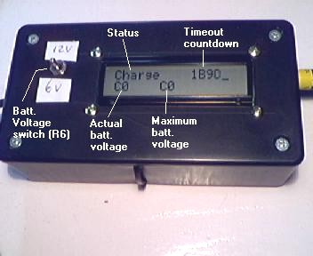 This battery charger charges a NIMH 5-pack battery used in the BiPed robot in less than 1 hour, and charges the 10-pack NiCd used in the Snuf robot in about 30 minutes. To prevent overheating of the battery, the charging current is turned off when the slope of the battery-voltage turns from positive into negative. A second termination-criterion of the charging process is provided for safety: the charge time is limited to about 1 hour.
Posted on Wednesday, May 26, 2010 • Category: FM Radio / Receivers
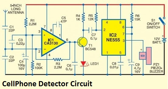 This handy cell phone detector, pocket-size mobile transmission detector or sniffer can sense the presence of an activated mobile cellphone from a distance of one and-a-half meters. So it can be used to prevent use of mobile phones in examination halls, confidential rooms, etc. It is also useful for detecting the use of mobile phone for spying and unauthorized video transmission.
Posted on Wednesday, May 26, 2010 • Category: FM Radio / Receivers
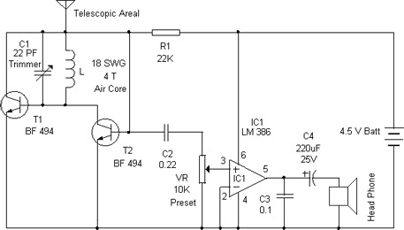 Perhaps this is one of the simplest and smallest FM Receiver that can receive the FM stations available locally. Its simple design makes it ideal for a pocket sized FM receiver. The output of the receiver drives a head phone.The circuit works off a small 4.5 volt battery or two 3.6 volt Lithium button cells.
Posted on Saturday, May 22, 2010 • Category: FM Transmitters
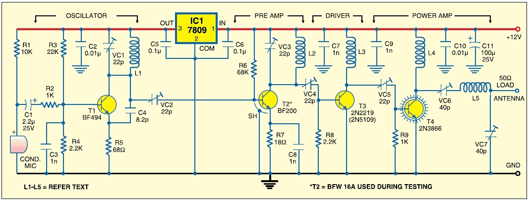 This FM transmitter circuit uses four radio frequency stages: a VHF oscillator built around transistor BF494 (T1), a preamplifier built around transistor BF200 (T2), a driver built around transistor 2N2219 (T3) and a power amplifier built around transistor 2N3866 (T4). A condenser microphone is connected at the input of the oscillator.
Posted on Thursday, May 20, 2010 • Category: Miscellaneous
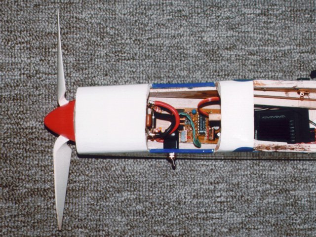 This electronic speed control (ESC) for brushed motors combines the features of two of my earlier designs. One was a high-rate 30A ESC with a brake, and the other a high-rate 12A ESC with a BEC (receiver battery eliminator circuit).
Posted on Thursday, May 20, 2010 • Category: Antennas
 A modified version of the simple dipole is the folded dipole. It has two half-wave conductors joined at the ends and one conductor is split at the half-way point where the feeder is attached.
If the conductor diameters are the same, the feedpoint impedance of the folded dipole will be four times that of a standard dipole, i.e. 300 ohm.
The height above the ground
The height of an antenna above the ground, and the nature of the ground itself, has a considerable effect on the performance of an antenna.and its angle of radiation. See PROPAGATION
A dipole antenna can be arranged to operate on several bands using other methods. One way is to install "traps" in each leg.
Posted on Thursday, May 20, 2010 • Category: Power Supplies
This is a 1.2 - 12 V, max 1A power supply with a low voltage indicator LED. The indicator part incluedes three diodes and one LED. For example you are charging a battery, you can observe the charge status at that moment. Another advantage of this circuit, when the drawn current exceeds 1A (practically 0.85A), the current protector in LM317 intervens and LED indicator warns you about the very low output voltage.
Be careful while choosing the transformer. Most of the products are specified as 10VA but their outputs are not as said.
Another good property of this circuit is the mains noise does not pass to the DC part.
Posted on Thursday, May 20, 2010 • Category: Video
Digital VGA switch for switching between two PC monitors with MAX465 IC.
Circuit-Zone.com © 2007-2026. All Rights Reserved.
|