Circuit-Zone.com - Electronic Projects
Posted on Tuesday, February 18, 2014 • Category: FM Transmitters
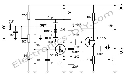
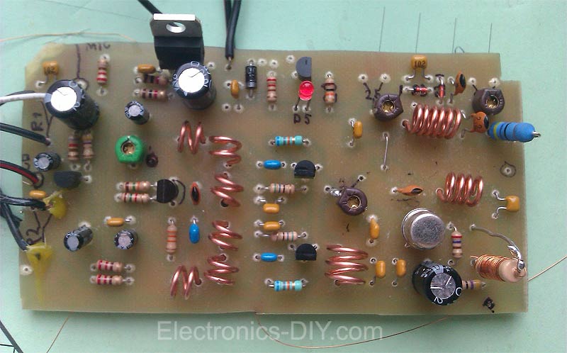
Here's FM transmitter for commercial FM band that provides 18 watts of power. Since the electronic diagram is too large we decided to divide it into two parts. The first part is the actual FM transmitter while the second part is 18W RF amplifier. The circuit should be built on an epoxy printed circuit board with the upper face components reserved for interconnecting tracks and the bottom solder to the ground plane. If powered by 14V and 2.5A transmitter outputs 15W of power, whereas 18V and 3.5A will provide 18W. BB110 variable capacitor connected to the collector of transistor BF199 adjusts the transmission frequency of the circuit. 2K2 potentiometer serves as fine tuning. Once the output frequency is adjusted amplifier variable capacitors must be adjusted for maximum output power one stage at a time. All adjustments must be made with 50 Ohm dummy load connected to the output of transmitter.
Posted on Friday, February 14, 2014 • Category: Solar Circuits
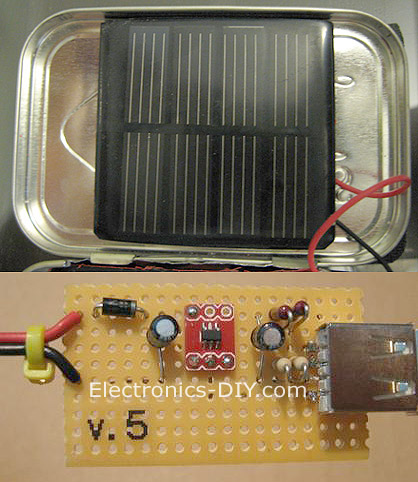 As the world around us becomes more and more environmentally conscious, alternative energies such as solar power are becoming more and more popular. The following solar charger is very simple and inexpensive to build and could be used to charge cellphones, tablets and other USB devices. 6V solar panel could be easily salvaged from outdoor garden lights. Solar charger uses REG113-5 efficient low dropout regulator that only loses 250mv of forward voltage. Linear style regulators such as a LM7805 or LM317 type voltage regulators lose as much as 2-3V and can not be used in this application. Optionally you may also add four-resistor voltage divider to charge an iPhone or iPad.
Posted on Tuesday, January 28, 2014 • Category: AC / DC Innveters
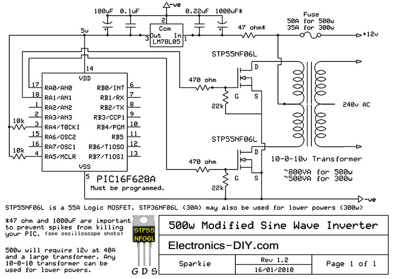 Here is a simple but powerful, stable and efficient schematic diagram for a 500W modified sine wave inverter circuit. Originally I used a 555 timer and a CD4017 decade counter to produce the modified sine wave, but then I thought a simple PIC micro controller with its internal clock would produce a stable 50Hz/60Hz frequency without the need for two ICs. As you can see its a very simple circuit. 220V transformer should be used for 220V voltage output. For 110V voltage output use transformer with 110V rating.
Posted on Wednesday, January 22, 2014 • Category: Power Supplies
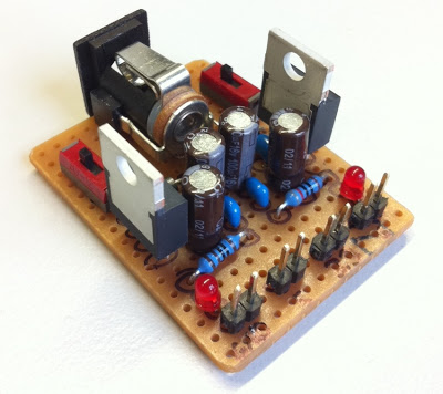 I normally use a USB port as power supply for my projects but some ICs need 3.3V instead of 5V. Therefore I decided to build this small dual power supply. Power supply uses two low dropout voltage regulators that provide up to 800mA of output current and come in TO-220 package. LD1117V33 is used for 3.3V and LD1117V50 for 5V. Input voltage is 6V-15V and both regulators can be switched on/off individually.
Posted on Sunday, December 29, 2013 • Category: FM Transmitters
 Veronica 1W FM transmitter is an easy to build transmitter. Veronica is also known for frequency stability, clean FM signal and uses no integrated circuit. The Veronica oscillator is actually formed from 2 oscillators which operates somewhere around 50 MHz in anti phase and the 2 signals are combined to form 100MHz FM radio signal. This kind of circuit design is stable and is amplified up to 1W by 2n4427 transistor. Veronica transmitter is equipped with a mini-mixer and so you may forget an external mixer. This consist from T1 transistor which amplifies the microphone signal before it is combined with cd-player audio or PC signal. R1 and R2 are potentiometers (variable resistors) used to adjust the audio level. The component between R8 and C21 represents the oscillator wich generates radio signal. D1 is a varicap diode (like a variable capacitor or trimmer) controlled by audio signal. C12, C13 and L1 determines the frequency.
Posted on Sunday, December 29, 2013 • Category: LED
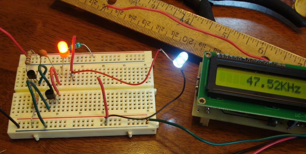 The "Joule Thief" circuit that does not use a transformer to power LED from a single 1.5V battery cell. The circuit consists of two bipolar transistors, coil, two resistors and capacitor to generate higher voltage through 50KHz frequency to power an ordinary LED. Entire circuit draws only about 15 milliamps.
Posted on Wednesday, December 18, 2013 • Category: FM Transmitters
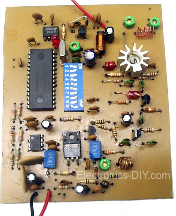 Following 1W PLL transmitter exciter provides stable, low noise operation. Transmitter uses a PLL frequency synthesizer built with MC145152 which covers the FM band in 100kHz steps. The VCO uses MV2109 varicap diode to automatically tune to selected frequency via SW1 dip switch. output stage uses 2N4417 RF power transistor and provides 1W of RF power. With good antenna expected transmission range is 2km. Transmitter may be built on a double sided PCB, with top side copper left mostly undisturbed as a ground plane. The copper is removed only around non-grounded pins. The ground connections can be soldered on the top side, so it’s not necessary to have plated-through holes.
Posted on Friday, December 13, 2013 • Category: LED
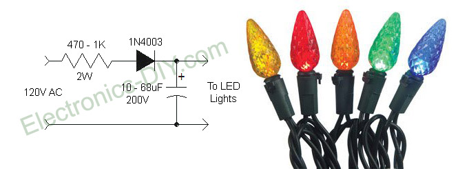 I like the idea of using LED Christmas lights because they look cool and consume very small amount of electricity, but the flicker drives me crazy! That's because they are powered directly from 110V AC voltage instead DC voltage which makes them flicker 60 times per second. Here is a simple circuit that will completely eliminate LED Christmas lights flicker. The solution is to convert AC to DC voltage with resistor, rectifier diode and capacitor. Using 470 ohm - 1K resistor is very essential because it limits the current to 20mA and minimizes the voltage to about 80 volts. If we didn't use the resistor LEDs would be powered by over 50mA of current which is much more than what they need and that would definitely shorten their life. Note that lowering voltage does not reduce the brightness of the LEDs because when powered by DC voltage they are always on.
Posted on Thursday, December 12, 2013 • Category: FM Transmitters
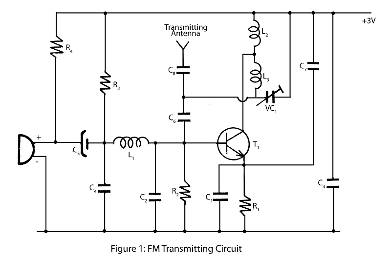 Here is a very interesting and simple FM transmitter used to transmit audio in the wide range up to 100M using only one transistor. The entire circuit of FM transmitter is divided into three major stages oscillator, modulator and amplifier. The transmitting frequency of 88-108 MHz is generated by adjusting VC1. The input audio generated by microphone is changed into electric signal and is given to base of transistor T1. Transistor T1 is used as oscillator which oscillates the frequency of 88-108 MHz. The oscillated frequency depends upon the value R2, C2, L2 and L3. Transmitted audio from FM transmitter circuit can be received by standard FM receiver.
Posted on Monday, December 9, 2013 • Category: Audio DAC
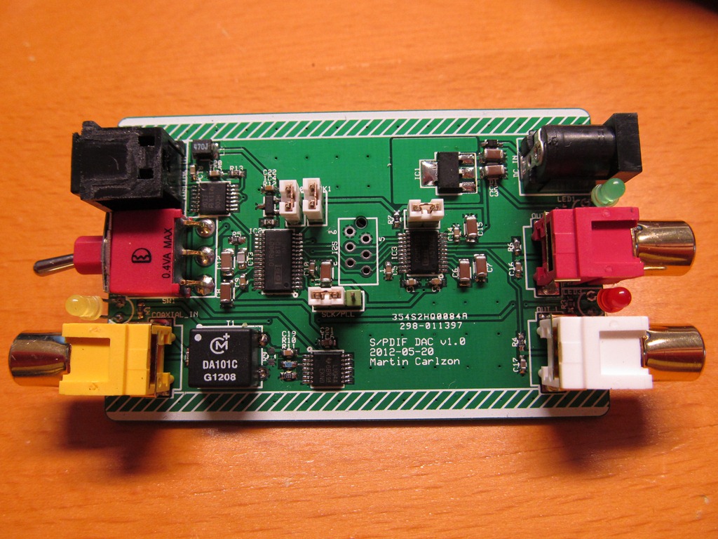 This DAC is based on latest 32bit/384K PCM5102 DAC chip and DIR9001 from Texas Instruments. Sound quality produced by PCM5102 DAC is surprisingly good, very smooth and airy, with great dynamics and excellent soundstage. It features both S/PDIF and optical inputs connected to DIR9001 low jitter digital receiver. PCM5102 uses a next generation architecture based on the PCM1792/4 TI's flagship DACs. It has 112dB SNR, with an integrated negative rail charge pump and line driver, so you don't need no opamps at the end or dual split supplies. Just a simple RC low pass filter is all that is needed. In addition, there's a fancy PLL involved that will autodetect I2S rate, configure the device, and generate it's own internal master clock so no need for external clock. Entire DAC is powered by only 3.3V from 1117-33 regulator and consumes only 20mA of power. Although PCM5102 DAC can be powered by 4-12V DC voltage, it's recommended to power it from a single 3.7V LIPO battery to achieve the best performance.
Circuit-Zone.com © 2007-2026. All Rights Reserved.
|
|
|