Circuit-Zone.com - Electronic Projects
Posted on Saturday, April 30, 2011 • Category: Remote Control
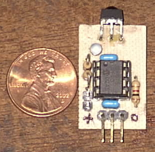
The function of the device is very simple. Any IR remote than can be programmed to use the Sony protocol will work. The module outputs the device code (TV/VCR/DVD/AUX) and the button pressed, so the device can be used on as many different projects as your remote has devices (usually four). The numeric keys output the number of the key (0 outputs a 0, etc.). The function keys all output unique numbers. Note that not all buttons are available depending on which device you have selected. The VCR setting seems to use most of the keys on the remote. Also note that the first key pressed after the device is powered up does not output what it should. All subsequent numbers are correct. Luckily, all of the numbers so generated make a number different than any of the key codes, so it doesn't cause any problem. This could even be used to let the device know if it has just been powered up or rebooted. I have no idea why it does this.
Posted on Friday, April 29, 2011 • Category: Headphone Amplifiers
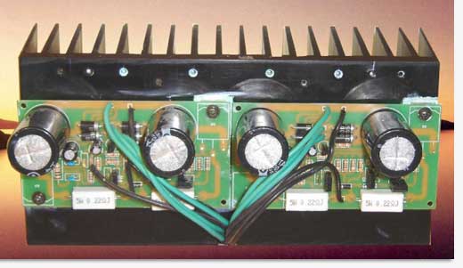 Here is a simple 100W HI-FI MOSFET Amplifier.
The main feature of this amplifier is a simple design and assembly. Simplicity of the circuit by looking at the circuit you expect amplifier to be simple. It should be noted that many hi-end amplifiers have a very simple but good quality designs. General technological theory is due to fewer parts, fewer problems. Additionally power to supplement your system is quite effective. Power supply transformer is very important. 8 Ohm output for a 35 - 0 to 35 V and at least 3 amps per power amplifier is recommended that a transformer can be transferred. Naturally, the two substations will be required for stereo use.
Posted on Thursday, April 28, 2011 • Category: Test and Measurement
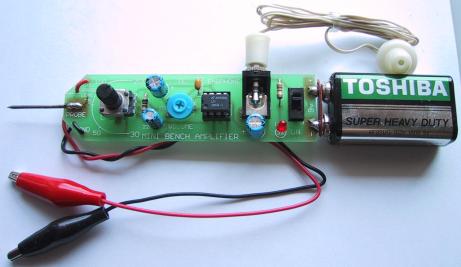 LM386 audio probe amplifier is an essential tool for troubleshooting audio stages in audio related circuits such as amplifiers, oscillators, function generators, phone circuits, radios and lots of our other projects. It is a very handy piece of test equipment that can be built on pre-drilled board and will make a perfect addition to your electronic collection. There are lots of things that can go wrong with an audio stage. It can produce distortion or a “hollow” sound, go weak or simply fail altogether.
Likewise tone circuits can present a number of faults and it is very handy to be able to “hear” what is going wrong.
It is not sufficient to measure the DC voltages on these stages. This only gives a partial picture of the conditions and does not tell you the quality of the audio being processed. To determine this you need a piece of test equipment that will let you see or hear what is being processed. Some of the projects you can test with the Mini Bench Amplifier are tone circuits while others are audio circuits. Tone circuits and audio stages are surprisingly difficult to test unless you have an audio probe or a oscilloscope. Oscilloscope is an ideal piece of equipment but if your budget does not extend this far, the next best thing is an audio probe.
Posted on Thursday, April 28, 2011 • Category: FM Transmitters
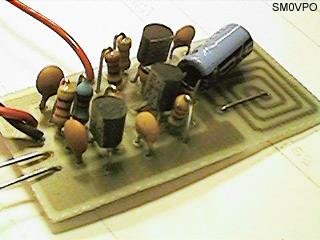 This FM Wireless Microphone has been a very popular project with beginners and experienced constructors alike. It has been used inside guitars and as the basis of a remote control system. I do however, receive many requests for a higher powered circuit and better microphone sensitivity.
This High Power FM Wireless Microphone has a better frequency stability, over 1 Km range and is good on microphone sensitivity. This has been achieved by adding an RF amplifier buffer (with 10dB gain) and an AF preamplifier to boost the modulation a little.
Posted on Thursday, April 28, 2011 • Category: FM Transmitters
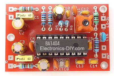 This FM transmitter design is a result of many hours of testing and tweaking. The goal was simple; to test many existing BA1404 transmitter designs, compare their performance, identify weaknesses and come up with a new BA1404 transmitter design that improves sound quality, has very good frequency stability, maximizes transmitter's range, and is fairly simple for everyone to build. We are happy to announce that this goal and expectations have been met and even exceeded.
The transmitter can work from a single 1.5V cell battery and provide excellent crystal clear stereo sound. It can also be supplied from two 1.5V battery cells to provide the maximum range.
One of the qualities of BA1404 FM transmitter is excellent frequency stability. This is mainly due to a use of high quality 3.5 turn variable coil. Tunable RF coils are ideal for precise frequency tuning because their magnet wire is halfway embedded within the plastic, which minimizes frequency drifts. Regular air coils are not preferred for professional broadcasting because the coil expands and contracts with temperature changes. That's the very reason why variable coil was chosen as a substitution for an air coil and a variable capacitor.
Posted on Thursday, April 28, 2011 • Category: Phone Circuits
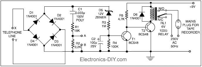 This circuit enables automatic switching-on of the tape recorder when the handset is lifted. The tape recorder gets switched off when the handset is replaced. The signals are suitably attenuated to a level at which they can be recorded using the ‘MICIN’ socket of the tape recorder.
Points X and Y in the circuit are connected to the telephone lines. Resistors R1 and R2 act as a voltage divider. The voltage appearing across R2 is fed to the ‘MIC-IN’ socket of the tape recorder. The values of R1 and R2 may be changed depending on the input impedance of the tape recorder’s ‘MIC-IN’ terminals. Capacitor C1 is used for blocking the flow of DC.
The second part of the circuit controls relay RL1, which is used to switch on/off the tape recorder. A voltage of 48 volts appears across the telephone lines in on-hook condition. This voltage drops to about 9 volts when the handset is lifted. Diodes D1 through D4 constitute a bridge rectifier/polarity guard. This ensures that transistor T1 gets voltage of proper polarity, irrespective of the polarity of the telephone lines.
Posted on Thursday, April 28, 2011 • Category: Sensors
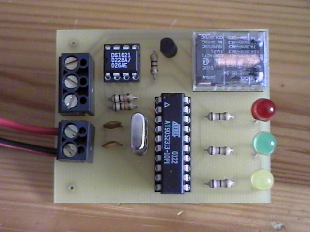 This circuit uses a Dallas DS1621 temperature sensor which indicates the temperature of the device. The temperature sensor has an thermal alarm output, which becomes high when the temperature of the device exceeds a user defined value. When the temperature drops below a user defined value, the alarm output becomes low. In this way any amount of hysteresis can be programmed. The values are stored in a special register of the device that is nonvolatile. The signal of the alarm output is amplified by a BC557 PNP transistor, that drives a relay that can switch a heater element or a blower on or off. The temperature settings and readings are communicated to/from the device over a simple 2-wire serial interface. An ATMEL 90S2313 microcontroller controls the serial communication to/from the DS1621.The microcontroller also controls three LED, only one of the LED's is on when the temperature is within a certain range. The range of the temperature in which the LED's are on can be set by the user in the program code. The circuit needs to be powered by a 5V power supply, which can be obtained from a wall-wart.
Posted on Tuesday, April 26, 2011 • Category: Sensors
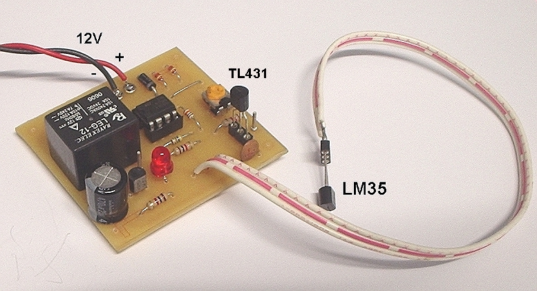 Here is a simple yet highly accurate thermal control circuit which can be used in applications where automatic temperature control is needed. The circuit switches a miniature relay ON or OFF according to the temperature detected by the single chip temperature sensor LM35DZ. When the LM35DZ detects a temperature higher than the preset level (set by VR1), the relay is actuated. When the temperature falls below the preset temperature, relay is de-energized. The circuit can be powered by any AC or DC 12V supply or battery (100mA min.)
Posted on Monday, April 25, 2011 • Category: Sensors
This circuit will turn on/off 12V DC fan or CPU fan when temperature above normal temperature.You can set turn on temperature by adjust VR1. This circuit use an NTC (Negative temperature coefficient)which is a thermistor is one in which the zero-power resistance decreases with an increase in temperature. So If temperature increase the voltage at pin 3 on LM311 will decreased .The resistance of NTC is about 10K at 25'c.
Posted on Thursday, April 21, 2011 • Category: Test and Measurement
The generator was build using XR-2206 function generator IC, which is capable to generate sine, square, ramp and pulse waveforms in frequency range of 0.01Hz to 1MHz. The amplitude and frequency is modulated by voltage (potentiometers). The example circuit from datasheet worked well.
Circuit-Zone.com © 2007-2025. All Rights Reserved.
|
|
|