Circuit-Zone.com - Electronic Projects
Posted on Saturday, February 12, 2011 • Category: Arduino
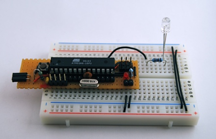
This Arduino can be used for old school prototyping as well. Just use it as a standard ATmega8 and program it with the ISP connector. And it is one of the cheapest Arduino boards, that you can get. Arduino is a great prototyping platform and most of you probably know already about it. If not, check out the Arduino pages and the Arduino playground and dive into it.
Posted on Thursday, February 10, 2011 • Category: Amplifiers
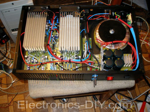 400W Stereo Audio Amplifier based on the original Marshall Leach involvement, but has made some improvements. Regarding the power supply voltage to the +-75V. VC comparing the performance of the modified Leach 700W/2R on one common board of both channels, as well as protection and control circuits for the fans. Compared to the 700W version a bit different in wiring. Because some things in the 700W version is completely tightened to perfection.
Posted on Wednesday, February 9, 2011 • Category: CNC Milling Devices
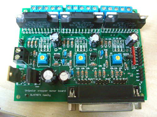 The electronics of a CNC machine is a simple but often confusing matter. In the picture (down) is shown the schema of a full system of four axes. Sometimes the breakout board is not present and the parallel port connected directly to the controllers. The main advantage of using single stepper controllers enable the user to connect different motors even in a mixed configuration (unipolar or bipolar steppers) tuning the CNC machine performances to the job to be done. A common and simple solution is the use of a board where the optoisolator (if any) and the controller/drivers are present in the same board, all-in-one. This solution allow a general quicker connection and a simple wiring but force the use of three or four identical (or similar) stepper motors.
Posted on Wednesday, February 9, 2011 • Category: Power Supplies
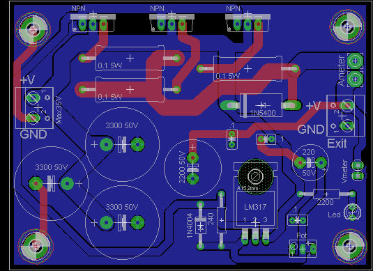 Here is a simple and economical 10A variable power supply with 1.2-30V. LM317 have been used to drive 3 NPN TIP41C transistors (or three 2N3055). Nothing to say about the project, it is really simple. The main supply must be connected to a rectified source (transformer + 20-30A bridge rectifier). For Q1,2 and 3 can be used any power TO220 transistor (TIP132C,TIP41C etc) or three external 2N3055 transistors.
Posted on Saturday, February 5, 2011 • Category: Stereo Encoders
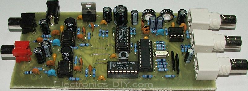 This stereo encoder is a halfway between analogue and digital processing. It combines the best from both domains to provide high-quality and easy to build device. The sampling frequency used in this stereo encoder is 97 times higher than the pilot tone frequency. This makes very easy to reject all spectral residues around the sampling frequency without affecting the main signal characteristics. Using of a microcontroller allows to build this stereo encoder with reduced part count and get excellent results in real operation. This stereo encoder advisedly does not contain any preemphasis circuit. Remember the key fact: a compressor/limiter/clipper device must be always present between the preemphasis circuit and the stereo encoder or modulator. Only this configuration ensures loud sound without exceeding the maximum frequency deviation limit (75 kHz). The stereo encoder is designed to provide really good sound. This always needs to use the compressor/limiter/clipper device where the preemphasis is precisely assured.
Posted on Saturday, February 5, 2011 • Category: FM Radio / Receivers
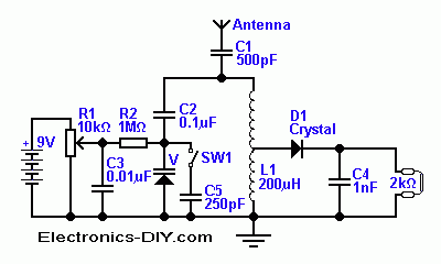 Traditionally, in a crystal detector radio tuned circuits, a mechanical type variable capacitor is used. For those of you who would like to eliminate this mechanical component, here is a modern version of the classic detector set. This radio, as shown on Figure 1, uses a varactor diode instead of the usual mechanical rotary device. The varactor is also known as a variable capacitance or a varicap diode. It provides an electrically controllable capacitance, which can be used in many different circuits. Varactors are small and inexpensive, which makes their use advantageous in many applications. Its disadvantages are a lower Q (quality), nonlinearity, lower voltage rating and a more limited capacitance range. A tuned circuit with a higher Q has a narrow pass-band that makes it better able to pick out a station of many equally strong. A lower Q tuned circuit has a wider pass band. It allows more neighbor stations through and makes listening to either radio stations frustrating. Frequency change with a varactor diode equipped tuned circuit is as simple as a voltage change.
Posted on Sunday, January 30, 2011 • Category: FM Transmitters
 So, I needed a small transmitter, which would allow me to transmit good, old music into my AM-only radios. So, one saturday afternoon I got into gear, designed and built a very crude, terribly non-optimized little transmitter. It's almost a joke expressed in electronics, full of poor design, so please don't think that this is the best I can do! You must see it as a quick and dirty 5-hour effort, because that's all the time the transmitter took to design, build, and test. Making this web page about it is taking much longer! I'm putting this thing on the web only because many people have asked me to do so, despite its crude design!
Posted on Sunday, January 30, 2011 • Category: Phone Circuits
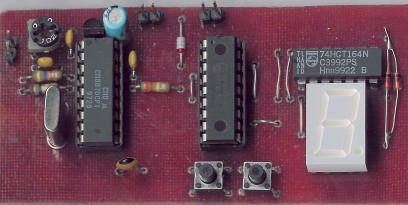 DTMF tone is mainly used in telecommunication technology, such as dialing a phone number, handling various services over the telephone, as a selective choice of radio stations, etc. The individual characters are assigned to different pairs of tones. The described decoder Received characters on the LED display, and stores them in memory, where they can be retrieved later. No matter allows for some sequences of characters on and off properly connected device. In practice, the decoder can be built as in the transmitter and connected to feeder line, the transmitter can then be remotely switched on and off, or you can run such a parameter indicating the traffic reports TA in RDS. The required sequence of tones may be part of the jingle.
Posted on Sunday, January 30, 2011 • Category: Oscilloscopes
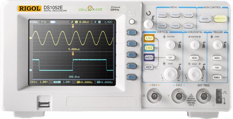 A scope probe is built to minimize ringing by adding resistance. A X1 is better than a piece of co-ax, but a X10 probe is more effective than a X1. A X10 probe has the effect of reducing capacitance by a factor of ten. The trade-off is that is also attenuates the signal by a factor of ten. That is, 1/10 the signal applied to the tip of the probe actually reaches the input of the oscilloscope.
Posted on Sunday, January 30, 2011 • Category: Phone Circuits
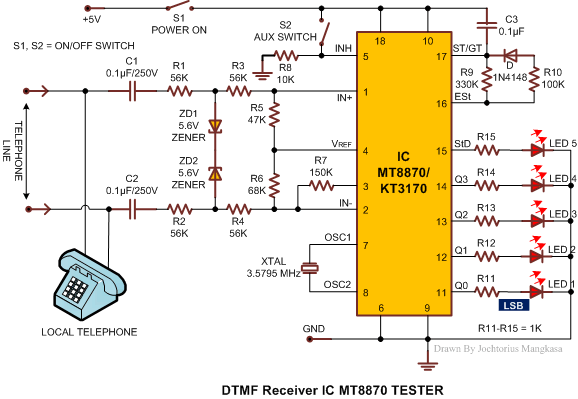 Today, most telephone equipment use a DTMF receiver IC. One common DTMF receiver IC is the Motorola MT8870 that is widely used in electronic communications circuits. The MT8870 isan 18-pin IC. It is used in telephones and a variety of other applications. When a proper output is not obtained in projects using this IC, engineers or technicians need to test this IC separately. A quick testing of this IC could save a lot of time in research labs and manufacturing industries of communication instruments. Here’s a small and handy tester circuit for the DTMF IC. It can be assembled on a multipurpose PCB with an 18-pin IC base. One can also test the IC on a simple breadboard. For optimum working of telephone equipment, the DTMF receiver must be designed to recognize a valid tone pair greater than 40 ms in duration and to accept successive digit tone-pairs that are greater than 40 ms apart.
Circuit-Zone.com © 2007-2026. All Rights Reserved.
|