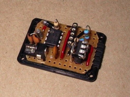
USB AVR Programmer for Atmel AVR microcontrollers. USB AVR Programmer is made of an Atmega8 and few components. The programmer uses a firmware driver that makes this programmer attractive to many amateurs.
Another thin why this programmer is so popular is because it is officially included and supported in WinAVR.
Once again lets see what this programmer is made off and how to set it up.
The core of USB AVR Programmer adapter is Atmega8 microcontroller clocked by 12MHz crystal. Soldered board is ready to be connected via simple USB cable with B type connector (Computer side needs A type of connector). Resistors R2 and R6 are current limiting resistors, that protect computer USB port. Resistor R7 helps computer to recognize device as LS (Low Speed). Diodes D1 and D2 indicates about data transfer. Header SV1 is compatible with STK200/300 just 4 and 6 pins are used for RXD and TXD (may be used for other purposes).
Posted on Friday, July 15, 2011 • Category:
Power Supplies
I’ve built myself my own universal, adjustable bench power supply.
This isn’t strictly astro stuff but the main reason I built it is to experiment with TFT backlight panels that I use for my lightboxes.
I needed 5V and 12V to play around with the inverter boards and figure out their pin-out. I considered buying a bench power supply. But prices were too high, especially for ones with adjustable voltages. So I decided to build my own.
This one has 4 outputs. One 5Volt, one 12V and two individually adjustable outputs going from about 1.5V to 19.5V. Each can draw up to 1.5Amp with a total of 3.5A for all together. The input is a standard replacement laptop power supply 20V, 3.5A. With a stronger external power supply the total output current can be higher, up to 1.5A per output. But currently the 3.5A is more than enough.
Each of the adjustable outputs has its own little voltmeter built in.
The fixed voltage regulators are based on a 7805 for the 5V and a 7812 for 12V. The two adjustable regulators are based on one LM317 each.
Posted on Friday, July 15, 2011 • Category:
FM Transmitters

This RF Amplifier designed for FM broadcast using a single 2SC1946 VHF Power Transistor. This 10-30W RF amplifier circuit provides an appropriate power boost with an input of 1-3 watt. Tower are 30 meters high will send signal surrounding air should be around 15 km. The layout of the 2SC1946 28 Watts FM broadcast RF amplifier has been created with Eagle. The pcb outline is 100 x 50 mm (width x height), all bitmaps have a resolution of 600dpi.Use FR-4 single sided photoresist epoxy pcb material for best results.
Posted on Thursday, July 14, 2011 • Category:
PIC

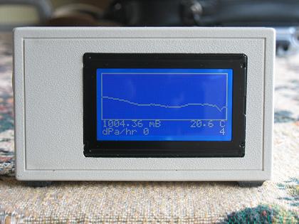
Here's a digital barometer that uses Atmega8 microcontroller and graphical LCD display. This project uses SCP barometer pressure sensor graphical LCD display connected to Atmega8 microcontroller. Graphical LCD displays latest 128 readings while one reading occur once in 20 minutes. You can see information of about two last days. Provided C source code can be customized to your liking.
Posted on Thursday, July 14, 2011 • Category:
PIC

This project uses a Microchip PIC microcontroller, a serial EEPROM and a thermistor to create a temperature recorder.
The temperature is measured and stored at user programmable intervals; this can be from 1 second to 256 seconds. The time interval is set by programming it and the start time into the EEPROM.
Most of the time the PIC will be asleep and the EEPROM IC is inactive. This gives a very low current consumption of approximately 50 uA or about 1 mAh per day.
The EEPROM used is 32kBytes which can store up to 32,000 measurements. This could be one measurement every 30 seconds for 11 days for example.
The combination of thermistor and analogue circuit gives a range of between about -40 °C and +100 °C although the linear range is between about -10 °C and +40 °C.
Posted on Thursday, July 14, 2011 • Category:
FM Transmitters
This is a very simple 5 watt CW TX based upon a TTL logic chip. There is just one "tricky" component and this is Cx. This component should have an impedance of about 10 - 50 ohms at the frequency of interest. If you wish to reduce the transmitter power, increase the value of Cx. It is Cx which causes the square wave from the output transistor to approximate a sine waveform. The value of Cx is the price of simplicity in this TX.
Circuit-Zone.com © 2007-2026. All Rights Reserved.