Circuit-Zone.com - Electronic Projects
Posted on Tuesday, October 27, 2009 • Category: FM Transmitters
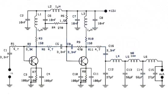
That RF Amplifier is for boosting small fm transmitters and bugs. It use two Philips 2N4427 and its power is about 1Watt. At the output you can drive any linear with BGY133 or BLY87 and so on. Its power supply has to give 500mA current at 12 Volts. More voltage can boost the distance but the transistors will be burned much earlier than usual.! In any case do not exceed the 15Volts. The Amp offers 15 dB in the area of 80Mhz to 110 Mhz. L4, L5, and L6 are 5mm diameter air coils, 8 turns, with wire 1mm wire diameter.An easy project, with great results.
Posted on Tuesday, October 27, 2009 • Category: Battery Chargers
« Atheros Drivers
ASUS Eee Car Charger
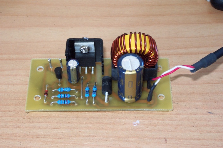
Building a 12v car charger for the ASUS Eee
The ASUS Eee is a fantastic ultra-portable notebook with almost everything required for geeks (and nothing that isn’t). Plus it features fantastic build quality and is very well priced. If you live in New Zealand you can get them from DSE; at the time of writing they are the exclusive supplier. I worked out it’s the same cost as importing one once you include all the duties and tax, plus you get the advantage of a proper NZ-style mains charger.
Anyway, being so small I thought it would be nice to be able to carry this around in the car. Unfortunately I couldn’t find a car charger available anywhere at the time so I decided to tackle the problem myself. As a bonus this provides an opportunity for an external high-capacity battery.
Commercial Equivalent
I thought at this stage it would be worth noting that a commercial car charger is now available for less than it cost me to build this from Expansys and is available in most countries (select your location on their site). It outputs 9.5v from 10-18v in at up to 2.5A
I’d actually recommend it over the design here is it seems to perform better at lower voltages (that one works down to 10V). However I have kept this page up as a reference for those who enjoy tinkering.
Design
The charger included with the Eee is rated at 9.5v, 2.315A. There isn’t a fixed voltage regulator available for this exact voltage, so the circuit needed to be designed around an adjustable regulator.
I decided to design the charger around the LM2576 “Simple Switcher” IC from National Semiconductor. There are tons of ICs like this available, many of which are a bit more efficient, however I selected this one because it is readily available and relatively cheap. It also has a lower drop-out voltage (~2V) than many other chips I looked at which is important when powering the device from a car or 12v SLA battery.
Posted on Wednesday, August 26, 2009 • Category: USB Interface Adapters
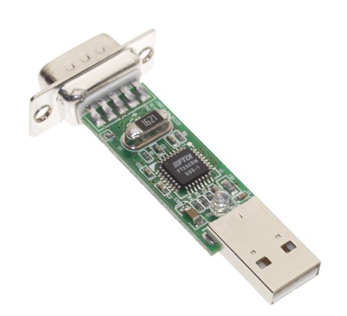 The USB to Serial adapter (converter) lets you use a serial PDA, GPS, cell, etc. with a standard USB port. This adapter is the easiest way to add a serial port to your computer. Many PDAs, digital cameras, GPS units, barcode scanners, and other equipment require a serial connection, and many newer computers don't come equipped with serial ports anymore.
Posted on Saturday, August 22, 2009 • Category: FM Transmitters
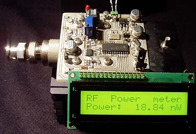 This watt meter project is very similar to my last wattmeter project. The main reason I made a new project is becasue I needed a unit which could handle higher power than 1W. I found a 50 ohm dummy load which could take 50W of power. Of course I could use attenuates for my 1W meter, but I prefered to build a new unit. The new thing with this project is that it will only display the power in Watt on the LCD display.
Posted on Saturday, August 22, 2009 • Category: Battery Chargers
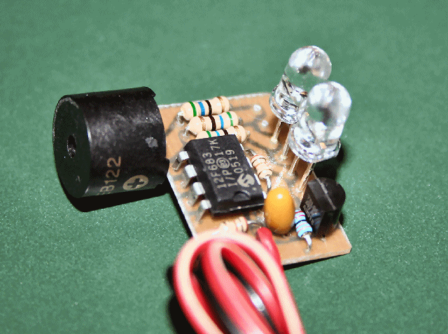 The Simple-Volt automatically detects the number of LiPo cells connected (assume charged pack) and continually monitors the battery voltage and compares it to the preset cutoff/warning voltage corresponding to the number of detected LiPo cells (9v for 3s, 12v for 4s and 15v for 5s... basically, 3 volts minimum per cell).
When the battery voltage is greater than the cutoff voltage +1v, the Green LED will be on solid. If the battery voltage is > cutoff voltage+.5 but < cutoff voltage+1v, the Green LED will slowly flash. If the battery voltage is > cutoff but < cutoff+.5v, then the Red LED will begin flashing. If the battery voltage < cutoff voltage, both Green and Red LEDs will flash very fast while also emitting an intermittent beeping sound from the peizo alarm buzzer.
Posted on Saturday, August 22, 2009 • Category: Amplifiers
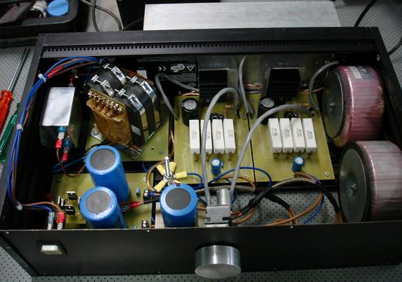 I was in my final 6 month work term with an electronics company as a trainee. Within this company there are a few audiophiles who are tube lovers and spend astronomical amounts of money on their audio equipment. My training supervisor had found Mark's Class A MOSFET Amplifier Project and suggested that I design a PCB and build this project as part of my training.
I followed the Class A MOSFET Amplifier Schematic with the following exceptions. Instead of the 2SK1058, I used the 2SK2221 mosfet which I had on hand. I compared the datasheets of the 2SK1058 and the 2SK2221 and the differences between the two were very small. The other change was to use a 6800 uF capacitor on the output instead of a 4700 uF capacitor.
Posted on Saturday, August 22, 2009 • Category: Power Supplies
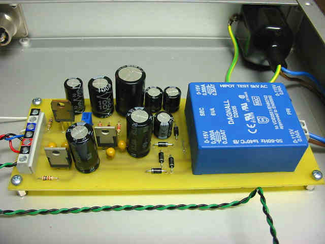 The main balanced power supply is constructed with the usual suspects, 7815 (pos 15 volt regulator) and 7915 (neg 15 volt regulator). These are fed from rectified AC via a PCB mount 6VA power transformer. I have use four diodes in a bridge rectifier configuration rather than a dedicated bridge rectifier as people have had trouble finding P04 and W04 rectifiers and it allows you to get esoteric with low noise switching diodes. I used the simple and easy to get IN4004 but some at Tech Talk have suggested more exotic devices.
Posted on Saturday, August 22, 2009 • Category: Power Supplies
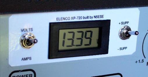 I frequently have a need for a variable supply when testing homebrew circuits, and the triple power supply is just what I need on the bench. With an amp out at 13.5 V, it will easily handle that QRP full-gallon. It even has 6 and 12 V AC available, for those rare filament-power circuits.
Posted on Saturday, August 22, 2009 • Category: Power Supplies
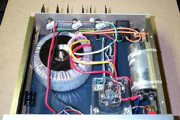 As is commonly the case, this supply was born of necessity. There is absolutely nothing special about the circuit, except that as shown, it is quite capable of up to 20 Amps intermittently or 10A continuous. Simply use a bigger transformer, bridge rectifier and more capacitors and output transistors
to get more current. The basic circuit should be good for up to 100A or so, using a 5A TO3 regulator IC, but it can obviously be increased further (if you really do need a 500A supply!).
Posted on Saturday, August 22, 2009 • Category: Test and Measurement
This new 50MHz Frequency Meter is autoranging and displays the frequency in either Hz, kHz or MHz. This makes the unit easy to read, as it automatically selects the correct range for any frequency between 0.1Hz and 50MHz and inserts the decimal point in the correct place for each reading.
The design is easy to build too, since it uses a programmed PIC microcontroller to do all the clever stuff. Apart from that, there's an LCD readout, a couple of low-cost ICs, two transistors, a 3-terminal regulator and a few sundry bits and pieces to complete the design.
Note that although we have specified this Frequency Meter at 50MHz maximum, most units will be capable of measuring frequencies somewhat higher than this. In fact, our proto-type meter was capable of making frequency measurements to above 64MHz.
Circuit-Zone.com © 2007-2025. All Rights Reserved.
|