Posted on Wednesday, October 6, 2010 • Category:
FM Transmitters
The important part of the circuit is formed of the Colpitts type oscillator. C3,C4,C5,C6,CD1-CD2 and L1 determines the frequency. BF982 and dual gate MOSFET are active parts in oscillator. When the input impedance of the MOSFET gate inputs are high, LC tank is not affected. However transistors force the LC tank and cause phase shift. Two driver stages are added to isolate the antenna from oscillator. First stage (BF199) amplifies the low signal of the oscillator and works as a constant load. The second stage (BFR90) amplifies the signal going through the antenna some more. A short copper wire can be used as an antenna here. Attaching a large antenna to this circuit is unnecessary because the output power is low.
Posted on Wednesday, October 6, 2010 • Category:
FM Transmitters

Here is a simple set up which will enable them to measure the out put power of their transmitter. All that they require is a good multimeter which has a sensitivity of 20k ohms/4 Watts which is adequate for low power transmitters. Many beginners trying out their skill with QRP TX, for the first time have to overcome many problems before they are able to come on the air. On usual complaint is that, every thing is working fine but the signal is not going out.
Posted on Wednesday, October 6, 2010 • Category:
FM Transmitters

This FM transmitter attaches in series to one of your phone lines. When there is a signal on the line (that is, when you pick up the handset) the circuit will transmit the conversation. In particular it will radiate from the phone line itself. It is a passive device - there is no battery. It uses the signal on the phone line for power. No aerial is needed - it feeds back the RF signal into the phone line which radiates it in the FM band. The frequency of transmission may be adjusted by the trimcap.
Posted on Wednesday, October 6, 2010 • Category:
Test and Measurement

The ESR meter is perfect for any electronics repair technicians, engineers or hobbyist. This handy meter measures electrolytic capacitor equivalent series resistance (ESR) in the circuit. ESR is a very important characteristic of capacitors greater than 1 microfarad. This meter makes measurements which are often impossible to check with standard digital capacitance meters.
Posted on Tuesday, October 5, 2010 • Category:
FM Transmitters

The PLL transmitter exciter has the functions of providing a stable, low noise, frequency-selectable RF signal and amplify it to a controllable output power sufficient to drive the power amplifier. It uses a PLL frequency synthesizer built with MC145151, which covers the FM band in 100kHz steps. The VCO covers only a few MHz without readjustment.
Posted on Tuesday, October 5, 2010 • Category:
FM Transmitters

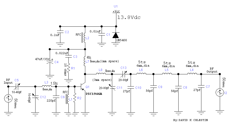
The 30 watt amplifier schematic shown below provides an appropriate power boost with an input of 4 watt up to 6 watts. The circuit is designed to cover 88-108MHz FM Broadcast Band. However, the circuit is very stable at my place and provides a clean-output through seven (7) element Butter-worth low-pass filter.
Posted on Tuesday, October 5, 2010 • Category:
FM Transmitters
Presented is a three stage 3W FM Transmitter Amplifier using 2SC9018, 2SC2053 and 2SC1970 transistors. The circuit is supplied by 12-14V DC voltage and requires at least 500mA of current.
Posted on Tuesday, October 5, 2010 • Category:
FM Transmitters
One of the most useful gadgets a video enthusiast can have is a low-power TV Transmitter. Such a device can transmit a signal from a VCR to any TV in a home or backyard. Imagine the convenience of being able to sit by the pool watching your favorite movie on a portable with a tape or laser disc playing indoors. You could even retransmit cable TV for your own private viewing.
Circuit-Zone.com © 2007-2026. All Rights Reserved.