Circuit-Zone.com - Electronic Projects
Posted on Wednesday, June 29, 2011 • Category: Amplifiers
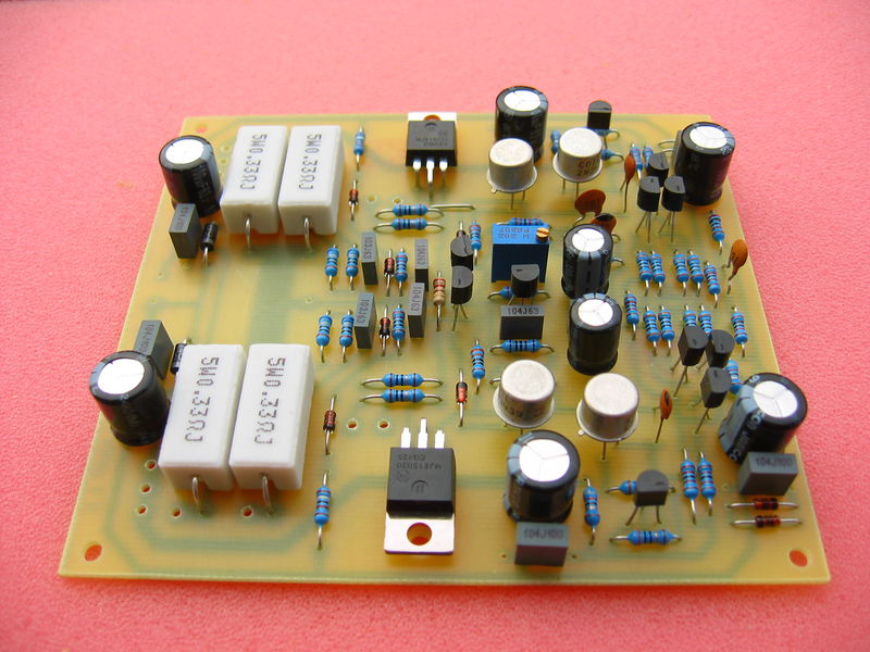
This article describes how to build 200W Leach Amplifier from Mr. Marshall Leach known like “The Leach Amp”. Article about building of this amplifier I found later in journal A_Radio Praktická elektronika 11/2002. For many years I looked for construction of HiFi amplifier wit a good parameters, enough power reserve and simple construction. I built a couple of amplifiers with integrated circuits MBA810, TDA2005, LM3886, but I was disappointed by their output quality and noise. I decide to built a classic construction with discrete components and bipolar transistors. Construction from Mr. Dudek was interesting, but I didn’t like used components and complexity. All of my requirements satisfied construction of the Leach Amp. Circuit author publicates in a February 1976 in american journal. From these days circuit was not practically changed. Little changes are described on authors page.
I succeeded to find almost all original components on our local market, which was a miracle. Only a bigger problem was a power transformer and filter capacitors. Recommended toroid transformer for power 200W to 4 ohms is 230V/2x 42V.
Posted on Tuesday, June 28, 2011 • Category: FM Transmitters
 Presented here is a 1.5 Watt FM Transmitter. A transmitter is an installation in which electrical oscillations are generated by an antenna as radio waves are emitted.Although there are a variety of channels exist in terms of size, application and frequency, each transmitter is an oscillator is present (usually crystal controlled) that an electric thrill, the carrier, with a constant frequency electricity.This is followed by one or more selective amplifier stages tuned oscillation circuits, which usually frequency multiplication is performed.Modulation can occur at low power, and even strengthening of the modulated signal to the power required to reach.Modulation can also occur at high power, when the carrier signal and separately reinforced.
Posted on Tuesday, June 28, 2011 • Category: Battery Chargers
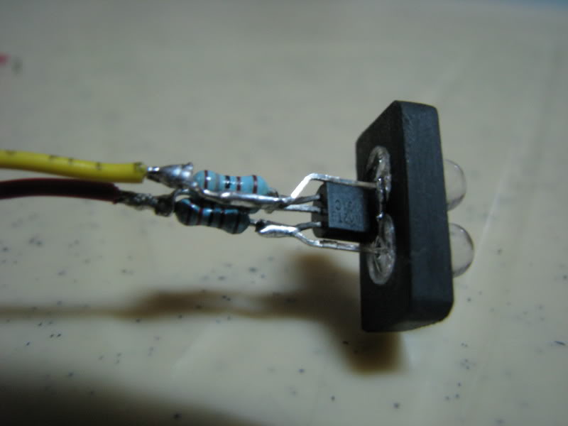 Lipoly batteries are great power source for our AEGs, they offer high current capacities and are available in different shapes and sizes that can fit virtually any AEG. But they have a downside, they are prone to failures when over discharged. Their nominal voltage is 3.7V (4.2V-full charge) but must not go below their critical voltage of 2.7V.
New development in AEG electronics protect the battery from going too low by either cutting the power or an audible warning that indicates low battery voltage. While saving up for the "Panther" or "Cheetah" SW-COMP, here is a cheap and easy to construct 11.1V lipoly lo-batt indicator.
Posted on Saturday, June 25, 2011 • Category: Power Supplies
 Here's variable power supply voltage regulator circuit based around LM317 that provides fully regulated output voltage between 1.25 and 37v with current up to 1A. In many cases we can manage with a suitable fixed voltage regulator such as 5v or 12v, but occasionally we need a non-standard voltage. In these circumstances the LM317 range of regulators proves to be very useful.
Posted on Friday, June 24, 2011 • Category: LED
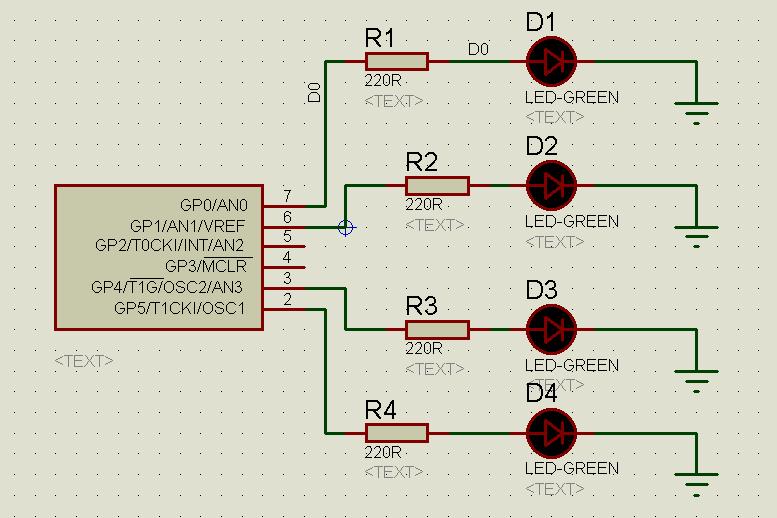 Here's a simple running LEDs circuit based around PIC 12F675. I'm begin in developer with MCUs and recently i bought some eletronics components. Then i using Proteus for assembling the circuit and MikroC for developer MCU. I am making the leds blink using PIC12F675, 4 resistors 220 ohm and 4 leds.
Posted on Friday, June 24, 2011 • Category: Amplifiers
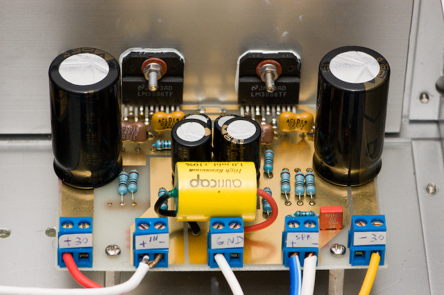 This is 100W LM3886 power amplifier. Since my DIY speaker is 4-ohm and somewhat difficult to drive, I want to have a more powerful amplifier to match with it. Therefore I designed this amplifier which uses two LM3886 per channel, in parallel circuit. This amp can deliver about 50W into a 8-ohm speaker and 100W into a 4-ohm speaker. This is a stereo amplifier and therefore 4 LM3886s are used. The LM3886 circuit is in a non-inverted configuration, so the input impedance is determined by the input resistor R1, i.e. 47k. The 680 ohm and 470pF resistor capacitor filter network is used to filter out the high frequency noise at the RCA input. The 220pF C4 and C8 capacitors are used to shot out the high frequency noise at the LM3886 input pins.
I used high quality audio grade capacitors at several locations: 1uF Auricap at the input for DC blocking, 100uF Blackgate for C2 and C6, and 1000uF Blackgate at the supply filter.
Posted on Friday, June 24, 2011 • Category: Battery Chargers
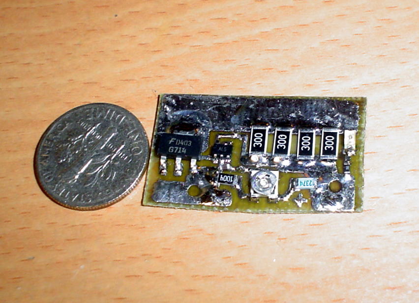 Simple LIPO saver board to throw onto lithium based batteries for overvoltage protection. It consists of a TLV3012 comparator with onboard reference, an voltage divider, load resistors, indicator LED and a transistor. It should turn on the transistor, and load LIPO battery cell when its voltage is >4.25V
Ive attached LIPO saver schematic. The diode represents the onboard reference in the comparator, eagle didn't have the device in its library.
Posted on Friday, June 24, 2011 • Category: Battery Chargers
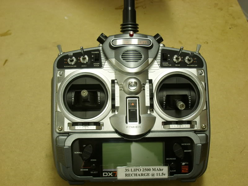 The presented battery saver or TL431 LiPo Saver is designed to prevent deep discharge of lithium polymer batteries. Decreases the cell voltage of a LiPo batteries below 2.4 volts will permanently damage the cell. When LIPO battery is about to reach the critical voltage a buzzer alarm is activated. I have built several of these for use as Tx alarm and they do SCREAM especially if you fit twin piezo sounders. TL431 is adjusted to sound off at pretty much any low voltage level you wish.
Posted on Thursday, June 23, 2011 • Category: FM Transmitters
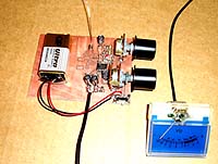 Most transmitter has several variable capacitors which are used to match impedance for transistors and antennas. I know people hate trimmers and so did I. The reason is that it is difficult to trim a system if you can't measure the performances.
To trim a transmitter you need to measure the output power.
Most transmitter are tuned with a dummy load of 50 ohm to substitute an antenna of 50 ohm.
Not everyone has a power meter, and how can you know that the antenna you connect is purely 50 ohm.
If not, the hole trimming is waste of time!
What you would like to do is to measure the radiated power out from the antenna you actually are going to use.
If you can measure the radiated energy field you can easy tune the system for max output field strength (max power).
So, how can we measure the radiated energy field?
The block diagram at right show you one easy way to measure the RF filed strength. To the left you find a dipole antenna.
The antenna should be cut to match the receiving frequency ...
Posted on Wednesday, June 22, 2011 • Category: FM Transmitters
This is 80W RF power amplifier that boosts FM Transmitter's power using 2SC2782 bipolar transistors in a tuned class C circuit. RF amplifier can be driven to full 80W power with less than 1 watt driving input power, so that a large gain margin results in this FM transmitter.
To obtain stability in this RF amplifier, I employed several techniques, such as placing the resonances of base and collector chokes far apart, damping the chokes with resistors, using RC combinations for absorption of unwanted frequencies, using feed trough capacitors for bypassing on the board, etc. It took some tweaking, but the amplifier ended up unconditionally stable.
Circuit-Zone.com © 2007-2026. All Rights Reserved.
|