Circuit-Zone.com - Electronic Projects
Posted on Thursday, May 28, 2015 • Category: FM Transmitters
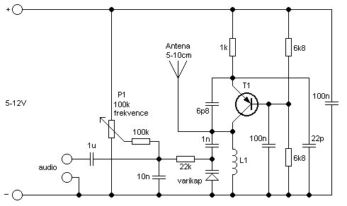
This simple transmitter allows you to broadcast on FM radio band 87.5 - 108 MHz. It consists of a simple oscillator with silicon planar RF PNP transistor. Directly to the oscillator an antenna is connected. Due to the large amplitude of RF voltage is sufficient antenna length of about 5-10 cm. I used insulated 7cm long copper wire 1mm diameter. I eliminated the tuning capacitor, which is usual for most bugs and miniature transmitters, because this greatly complicates the tuning. From my own experience I know that if you get closer to such capacitor, the operating frequency is changed. That's why I chose to use the voltage tuning using the Voltage Controlled Oscillator (VCO). Instead of tuning capacitor the varicap (capacitance diode) is used, which changes its capacity by changing the reverse DC voltage. We can tune the operating frequency by changing the DC voltage using the trimmer P1. Varicap also provides frequency modulation.
Posted on Sunday, May 24, 2015 • Category: FM Transmitters
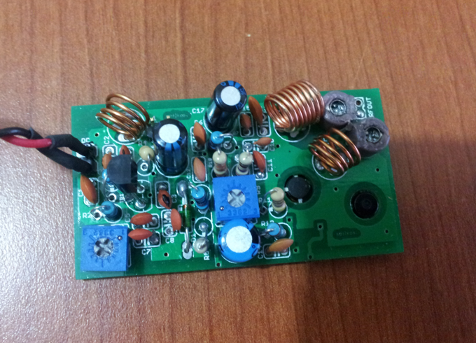 This simple 400mW transmitter broadcasts audio on 87.5 - 108 MHz FM radio band. With good dipole antenna transmission range up to 4km is possible. Frequency is selected by adjusting R1 potentiometer. Transmitter should be powered by regulated 12-14V power supply with at least 100mA current rating.
Posted on Thursday, April 23, 2015 • Category: FM Transmitters
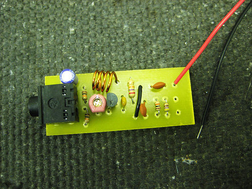 FM transmitters can be complicated to build, but not this one it’s about the easiest you can possibly make. And though the science of radio is well understood, there’s a magical, emotional quality about it that we don’t often stop to appreciate. You will not forget the first time you pick up a transmission broadcast from a device you soldered together, yourself, from a few bits of copper, carbon, plastic, and wire.
Posted on Thursday, March 12, 2015 • Category: FM Transmitters
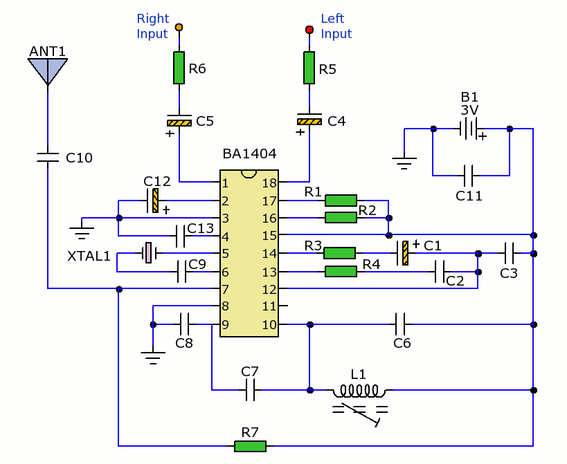 This is a small stereo FM transmitter. Output can be tuned from 88 to 108Mhz and the transmitter can be battery powered or be used with presented low voltage power supply. This circuit is based on the Rhom BA1404 datasheet. The maximum voltage should not exceed 3V. The IC can be driven from a 7805 Regulator with a couple of 1N4001 diodes to reduce the supply voltage to about 2.8 Volts. RF output power is typically 500mW but range depends upon antenna coupling and efficiency, environment and size of antenna. A small telescopic whip has an expected range of at leaset 100 metres or more.
Posted on Monday, March 2, 2015 • Category: Arduino
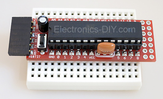 Arduino Prototype is a spectacular development board fully compatible with Arduino Pro. It's breadboard compatible so it can be plugged into a breadboard for quick prototyping, and it has VCC & GND power pins available on both sides of PCB. It's small, power efficient, yet customizable through onboard 2 x 7 perfboard that can be used for connecting various sensors and connectors. Arduino Prototype uses all standard through-hole components for easy construction, two of which are hidden underneath IC socket. Board features 28-PIN DIP IC socket, user replaceable ATmega328 microcontroller flashed with Arduino bootloader, 16MHz crystal resonator and a reset switch. It has 14 digital input/output pins (0-13) of which 6 can be used as PWM outputs and 6 analog inputs (A0-A5). Arduino sketches are uploaded through any USB-Serial adapter connected to 6-PIN ICSP female header. Board is supplied by 2-5V voltage and may be powered by a battery such as Lithium Ion cell, two AA cells, external power supply or USB power adapter.
Posted on Tuesday, December 30, 2014 • Category: FM Transmitters
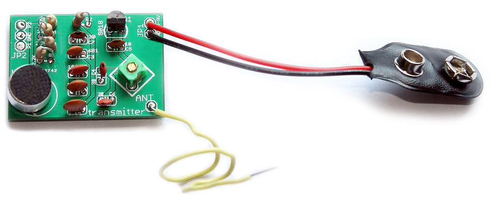 Here is a simple 76-110MHz FM transmitter that can transmit your voice or audio over an ordinary FM radio within the FM broadcast band. It can transmit both voice using microphone and music from any music player. Frequency is changed by adjusting 5.5 turn inductor coil. Transmitter is powered by 9V battery or 3V-9V power adapter. Transmission range is 100 meters but can be increased with better antenna or RF amplifier.
Posted on Wednesday, December 10, 2014 • Category: FM Transmitters
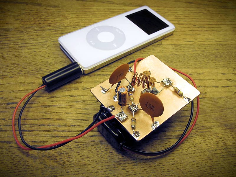 FM transmitters can be complicated to build, but not this one. It’s about the easiest you can possibly make. And though the science of radio is well understood, there’s a magical, emotional quality about it that we don’t often stop to appreciate. You will not forget the first time you pick up a transmission broadcast from a device you soldered together, yourself, from a few bits of copper, carbon, plastic, and wire.
Posted on Saturday, October 25, 2014 • Category: Stepper Motors
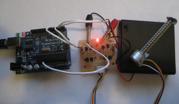 H-bridge is frequently used to control DC motors and stepper motors. When controlling a bipolar stepper motor, two full H-bridges are needed. There are many H-bridge ICs (like L298, MPC17529 and SN754410 which is a quad half H-bridge) for just that purpose. But if you are on a budget, you may want to consider building a dual H-bridge yourself. The following schematic shows a simple dual H-bridge using eight general purpose transistors (2N3904 and 2N3906). Given the maximum current of roughly 200mA, this circuit can be used to drive a small bipolar stepper motor operating between 5V and 12V, such as the stepper motors found in most floppy drives and CD / DVD drives.
Posted on Tuesday, August 26, 2014 • Category: FM Transmitters
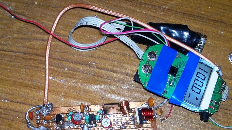 Presented FM transmitter is built around low power PLL transmitter and amplifier that boosts its signal all the way up to 6 Watts. The signal is amplified by three RF stages of amplification. In the first and second stages of the transmitter one of the best driver transistors were used 2SC2053. You can use the other transistors but only up to 500mW of power. In the third stage 2SC1971 RF transistor was used to achieve 6W of power. For making any RF transmitter circuit at least two meters are necessary, one is frequency counter and the other is RF field strength meter for which the schematic is provided.
Posted on Friday, August 22, 2014 • Category: Amplifiers
This is battery powered amplifier based on LM386 chip and has an input buffer that is feeding the inverting input. The input buffer helps to retain treble details going into the LM386 chip. It is powered from a single 9V battery.
Circuit-Zone.com © 2007-2026. All Rights Reserved.
|