Circuit-Zone.com - Electronic Projects
Posted on Wednesday, June 21, 2017 • Category: FM Transmitters
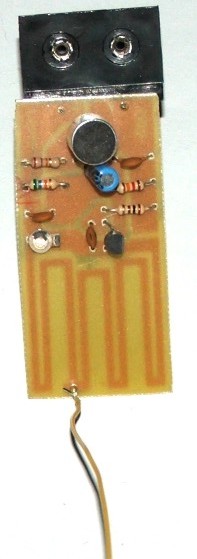
This circuit is basically an oscillator which runs at around 100 MHz. The most important parts of the oscillator are the transistor Q1 and the tuned circuit, which comprises the inductor Ll and the variable capacitor CV1. When the battery is first connected, a brief surge of current flows from the collector to the emitter of Q1, causing an oscillating (i.e: alternating) current to flow back and forth between Ll and CV1. An oscillating voltage therefore appears at the junction of Ll and CV1. The frequency of the oscillation depends on the values of Ll and CV1, so that varying the value of CV1 tunes the oscillations to the exact frequency required.
Posted on Wednesday, June 14, 2017 • Category: Arduino
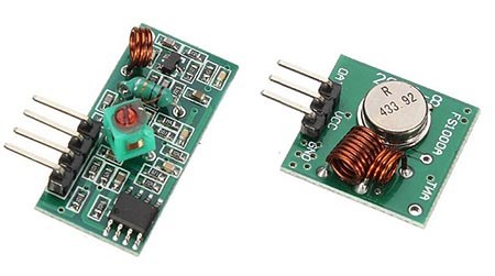 This post aims to be a complete guide for the popular RF 433MHz Transmitter/Receiver modules. I’ll explain how it works, show some features and share an Arduino project example that you can take and apply to your own projects.
Posted on Wednesday, March 22, 2017 • Category: FM Transmitters
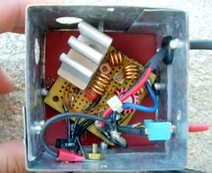 The following is a simple yet powerful 4W FM transmitter which is tunable to 88-108MHz frequency. Connect to your ipod/computer, etc. When this was first made, I only had a 2N2219A on hand, which resulted in a lower RF output. I have since swapped out the transistor for a 2N3866 for full 4W output at around 15VDC supply. In order to achieve a high output level, you will need a well tuned antenna, and a large heatsink to dissipate the heat from T2 transistor.
Transmitter was mounted in metal enclosure and works extremely well.
Posted on Wednesday, November 16, 2016 • Category: Test and Measurement
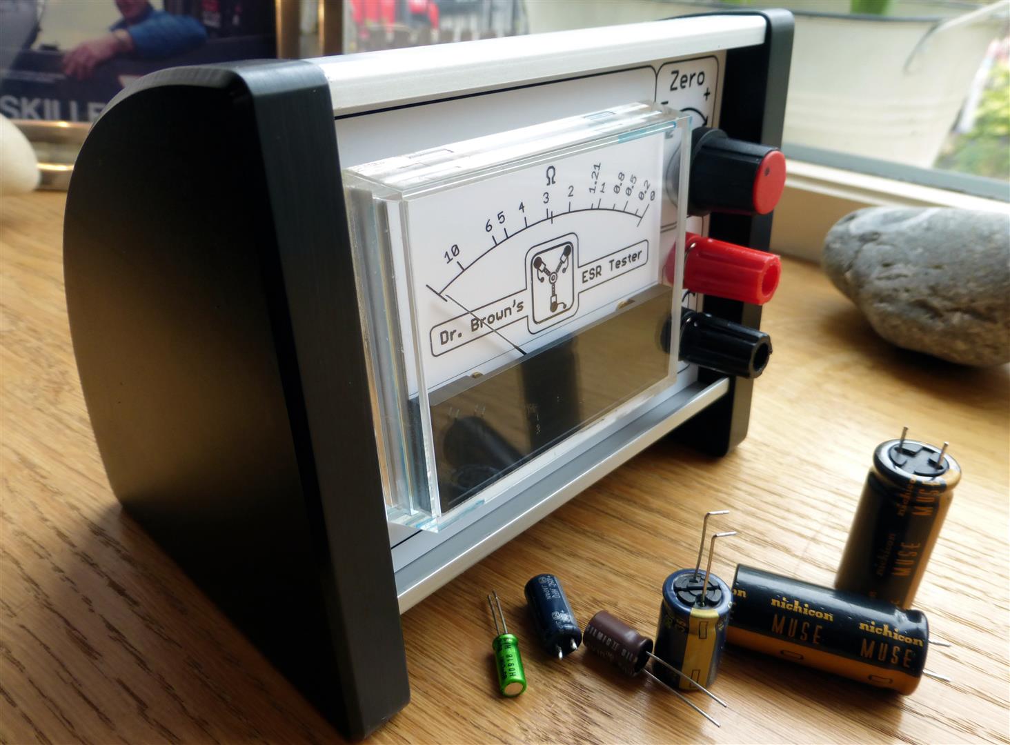 I finally got round to making my capacitor ESR tester this week after finding a nice simple 5 transistor version. Unfortunately, for me, the design was only SMD so, I decided to replicate his schematic in Eagle PCB using a through hole component design. I will not be going into much detail regarding ESR or Equivalent Series Resistance Meters as, there is already plenty of other sources of information on the subject. Yet, every tinkering knows capacitors are guilty of a lot of sins in electronics. Capacitors love to throw red herrings! They can appear physically fine (no bulge), show good capacitance and hide in circuit, standing to attention like the Queens Guards hiding shorts and high resistance under their big hats. This is where the ESR tester can be a saviour, with the ability to test for "out of specification" high resistance, within the capacitor. They can also be used to test "in circuit", without the need to remove every capacitor in the circuit.
Posted on Sunday, October 30, 2016 • Category: FM Transmitters
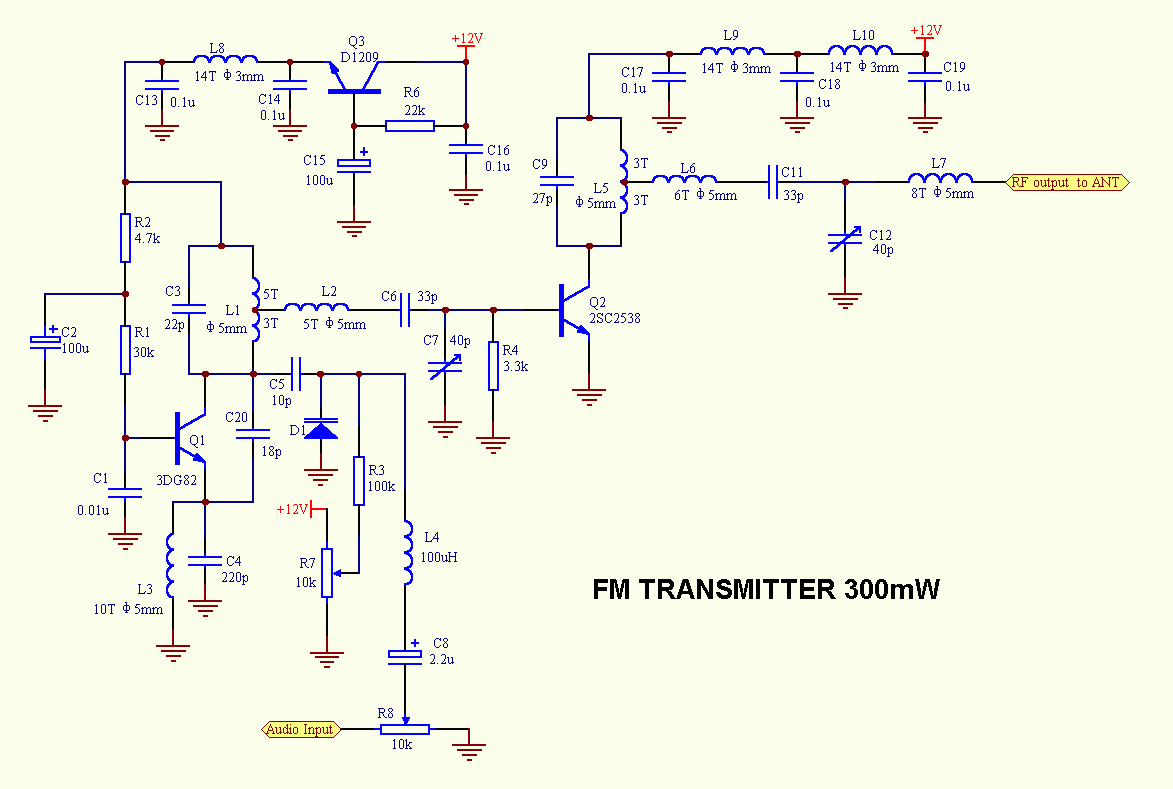 The above FM transmitter has RF output power of 300 mW and covers more than one kilometer distance. Frequency adjustment is accomplished with MV2105 varactor diode and R7 10K potentiometer. 2SC2538 is a class C 300mW amplifier.
Posted on Monday, October 24, 2016 • Category: FM Transmitters
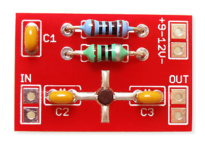 High performance low noise 500mW amplifier / booster for all low power FM transmitters such as BA1404, BH1417, BH1415, 433MHz transmitter modules, etc. The amplifier chip is an integrated circuit containing multiple transistor stages and all other parts conveniently within a single small package. Boosting your FM transmitter has never been easier and the output signal can also directly drive 2n4427 or 2n3866 transistors for 1W or 5W of RF output power.
Posted on Friday, October 21, 2016 • Category: FM Transmitters
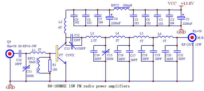 The power amplifier boosts 88-108MHZ 1-2W FM transmitter's power to 15 W. It includes multi-level low pass filter and has a high conversion efficiency with strong Yi-wave suppression. With good antena expected transmission coverage is at least 15Km. It uses high power 175 MHZ 4A 25W 2SC1972 RF transistor that must to be mounted to heatsink for proper heat dissipation.
Posted on Friday, September 30, 2016 • Category: Power Supplies
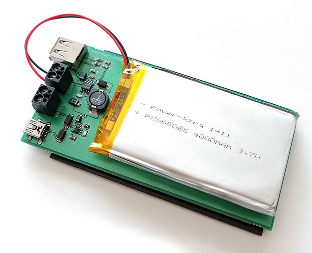 Solar energy is renewable, free, widely available and clean form of energy. It is considered as a serious source of energy for many years because of the vast amounts of energy that is made freely available, if harnessed by modern technology. Many people are familiar with so-called photovoltaic cells, or solar panels, found on things like spacecraft, rooftops, and handheld calculators. The cells are made of semiconductor materials like those found in computer chips. When sunlight hits the cells, it knocks electrons loose from their atoms. As the electrons flow through the cell, they generate electricity.
In this project, we are building a power bank which harvests energy by using a solar panel. The energy gained by the solar panel is stored in a LiPo battery. Then the battery is used to supply a stable 5V which is used by USB gadgets. The power bank can also be charged by an external 5V source. The best thing for this power bank during day that you don’t need to remember to charge it. It charges itself by using the sunlight and you don’t come up with an empty bank.
Posted on Thursday, June 30, 2016 • Category: Frequency Wave Generators
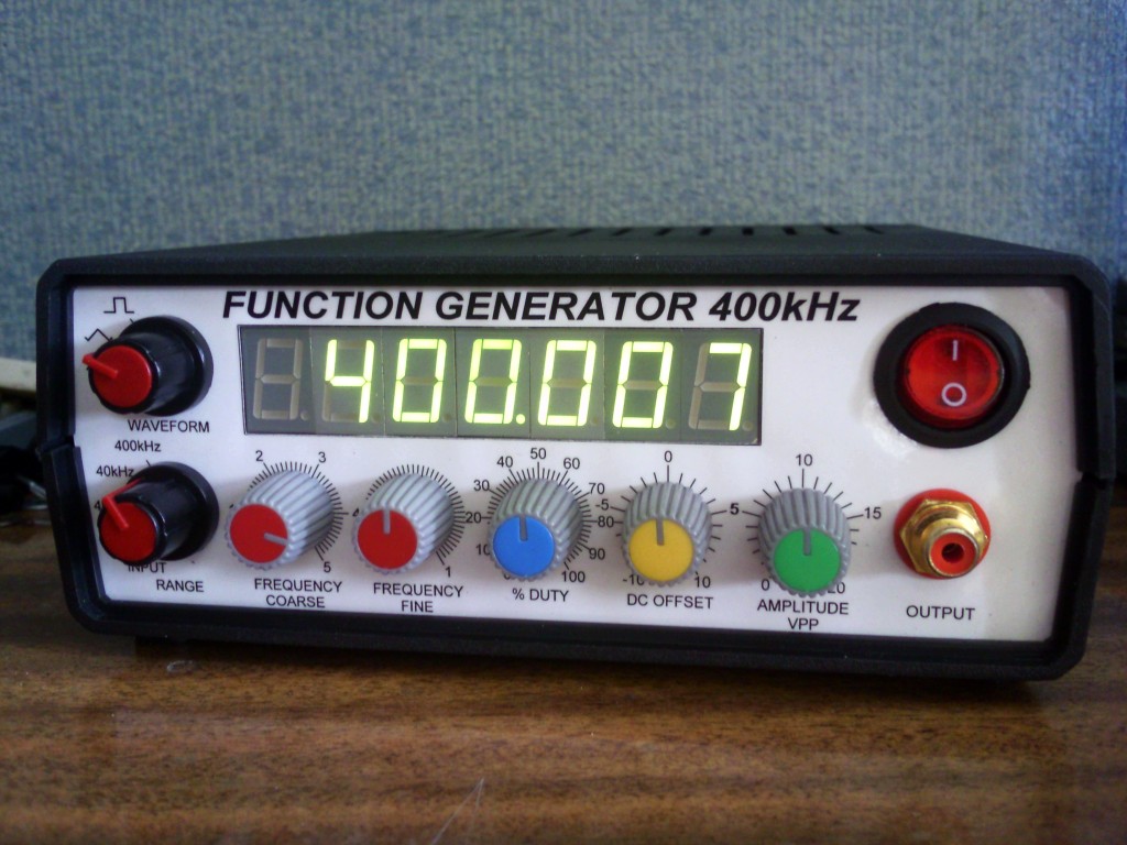 Function generator with adjustable frequency from 0 Hz to over 400 kHz, adjustable amplitude, DC offset, duty, and of course the function selection – square, triangle, and sine. Generator based on good old ICL8038 integrated chip generator that gives pretty good shaped signals as for amateur purposes. This circuit has been designed a little differently than ICL’s note or other similar circuits are suggesting. I tested a bunch of different configurations with different peripherals and chosen the best – so to get good waveshape at 400kHz. I got rid of some of the elements, I added my own solutions. The two ICL chips that i have can oscillate around up to 420-430kHz, and practically we can get good waveforms up to that frequency.
Posted on Friday, June 24, 2016 • Category: FM Transmitters
 The proposed long range transmitter circuit really is very steady, harmonic free design which you can use with standard fm frequencies between 88 and 108 MHz.
This will likely encompass 5km spectrum (long range). It includes an extremely consistent oscillator for the reason that you employ LM7809 stabilizer that is a 9V stabilized power source for T1 transistor and for frequency realignment that may be reached by means of the 10K linear potentiometer. The output strength of this long range rf transmitter is approximately 1W. Transistor T1 is employed as an oscillator stage to present a small power steady frequency. To fine-tune the freq. apply the 10k linear potentiometer this way: should you moderate, in the direction of ground, the freq. would probably decrease but when you fine-tune it in direction of + it would climb. Essentially the potentiometer is needed just as a flexible power source for the a pair of MV2019 varicap diodes. Both of these diodes function as a changeable capacitor whilst you regulate the pot. By tweaking the diode capacitance the L1 + diodes circuit renders a resonance circuit for T1. Feel free to employ transistors similar to BF199, BF214 however be careful not to use BCs. At this point you don’t receive yet the long range fm wireless transmitter due to the fact that the electric power is fairly reduced, a maximum of 0.5 mW.
Circuit-Zone.com © 2007-2025. All Rights Reserved.
|