Circuit-Zone.com - Electronic Projects
Posted on Monday, October 29, 2018 • Category: FM Transmitters
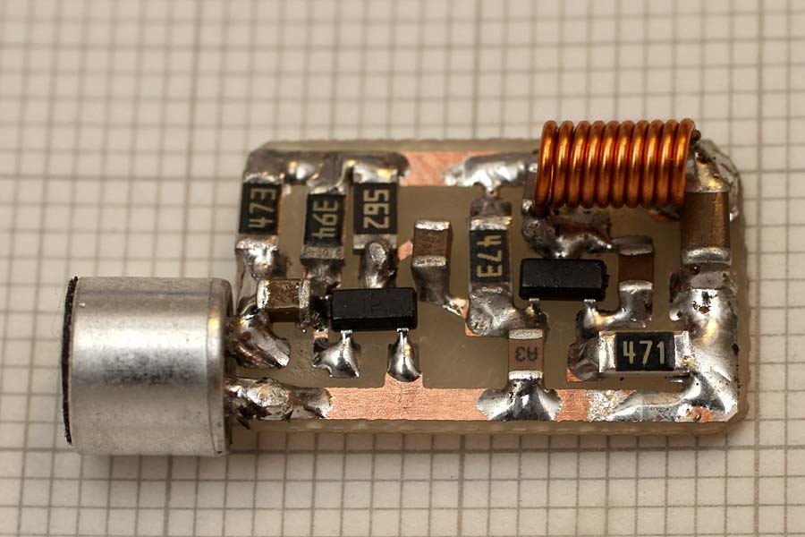
This tiny 88-108Mhz FM transmitter bug measures just 10mm x 17mm in size and as you can see in the photos the biggest components are just the microphone and the battery. You can use a small microphone from an older cell phones, they are small in size and have an excellent sensitivity. For an effective power supply the 9V battery (Duracell) is excellent and allows several hours of battery life, but if you want to have a smaller size it is better to use 2 or 3 lithium cells like the 2032 used in PCs. The circuit works well from 3 to 12V, the maximum range is obtained with 12V and a piece of 40-60cm cable as an antenna.
Posted on Monday, September 10, 2018 • Category: FM Transmitters
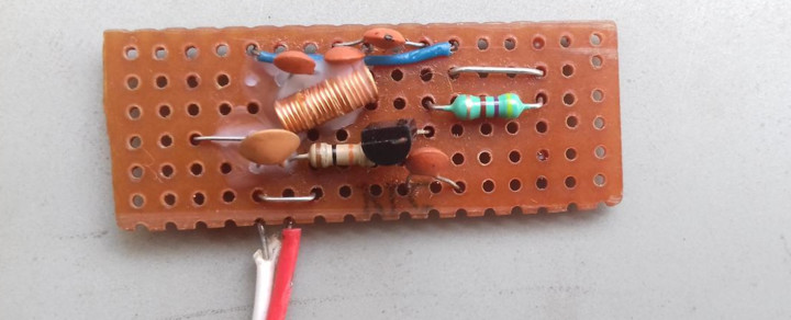
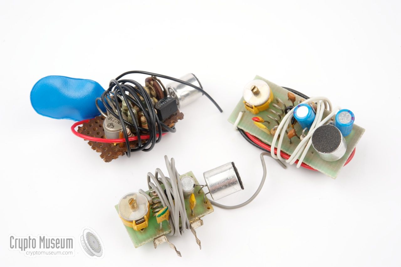 In the mid 1970s large numbers of small FM transmitters, operating in the FM radio broadcast band (88-108 MHz) appeared on the market. It started with a self-build kit from the Danish manufacturer Jostykit that allowed everyone to build a small FM transmitter for a few Euros. Such transmitters generally consist of a single transistor oscillator with a simple resonance circuit, sometimes with an extra transistor that is used as audio pre-amplifier. The image shows a few examples that were available in European electronics shops in the mid 1970s. The transmitter shown here was built in the mid-1970s and measures just 1 x 2 cm. When properly built, it may have a range of several kilometers.
Posted on Wednesday, July 11, 2018 • Category: FM Transmitters
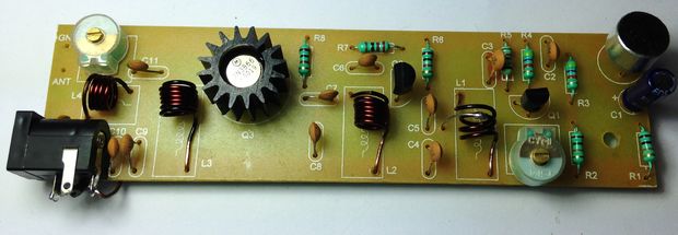
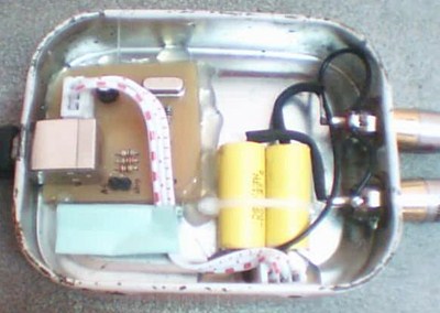
 This is a simple, portable transmitter operating in the 88-108 MHz FM band. You may use it to run your own private neighborhood radio, just replacing the microphone capsule with a male audio jack connected to your pc or MP3 player. You may also use this as a spy transmitter, but be reasonable in that case. It's rated for 1 Watt, so you can listen to it even from a few kilometers, with a good antenna and not too much obstacles in the way.
Posted on Tuesday, June 19, 2018 • Category: Audio DAC
 The following is a simple USB DAC Soundcard. It uses PCM2707 that incorporates USB interface to communicate with the computer and audio DAC all in one chip.
Posted on Saturday, May 26, 2018 • Category: Power Supplies
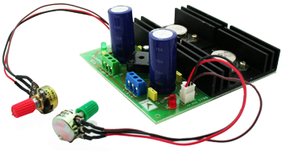 This project is a solution to power up most of devices or projects requiring dual (+/-) adjustable power supply. The circuit is based on LM317 positive and LM337 negative voltage regulators. LM317 series of adjustable 3 terminal regulator is capable of supplying in excess of 1.5A over a 1.2V to 30V DC output range, due to TO3 package of IC and large heat sink the power supply can handle maximum load current.
Posted on Wednesday, May 2, 2018 • Category: FM Transmitters
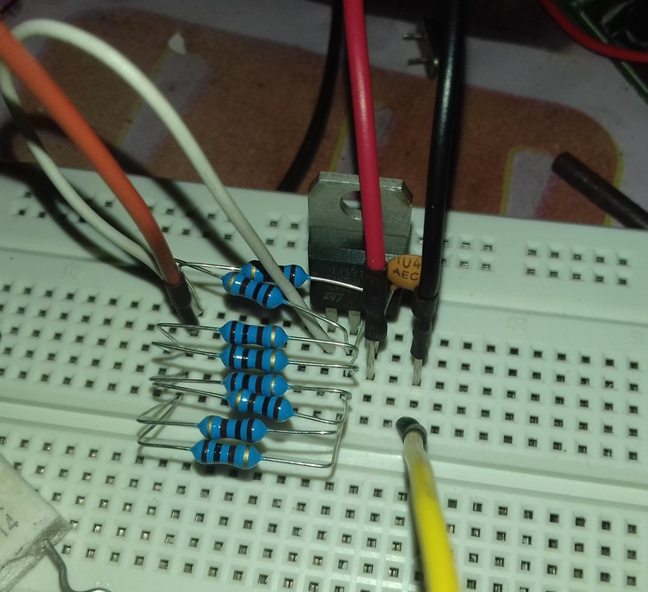
 FM transmitter circuit projects are indeed quite popular among electronics hobbyists / students. But the frustrating part is most transmitters refuses to work at all, and secondly the internet is full of crappy transmitter circuits. Designing a stable FM transmitter circuit is rather a difficult job, many calculations are involved their. There are also some construction error and component value tolerance. Here you can find a reasonably stable and well tested transmitter that actually works.
Posted on Monday, March 19, 2018 • Category: FM Transmitters
 This FM Transmitter is stable and has output power of 15-18 watts. You don't have to understand the precise working of the transmitter to build it. But some basic information won't harm. A transmitter alone is, as you probably know, is not enough to start your radio station. In the simplest form you need 4 things. First an input device such as an amplifier you also use with your home stereo. You need a regulated power supply. In this case a 14-18 Volts 2.5-3.5 Ampere. One of the most influential things you need is antenna and coax cable. And finally the transmitter itself. Transmitter is divided into two main parts; the oscillator and the amplifier. The oscillator converts electric sound information into electromagnetic waves. The amplifier gives these waves a bigger amplitude.
Posted on Monday, November 13, 2017 • Category: Power Supplies
 A constant current source source can supply a fixed current to a load regardless of input voltage or load change. LM317 / LM350 / LM338 constant current source is one of the simplest design. The LM317 is quite useful as a constant current source, works on a wide input voltage range, from 3V up to 40V. So, here’s the LM317 based constant current source, it’s design and a little about it’s working principle.
Posted on Monday, October 16, 2017 • Category: FM Transmitters
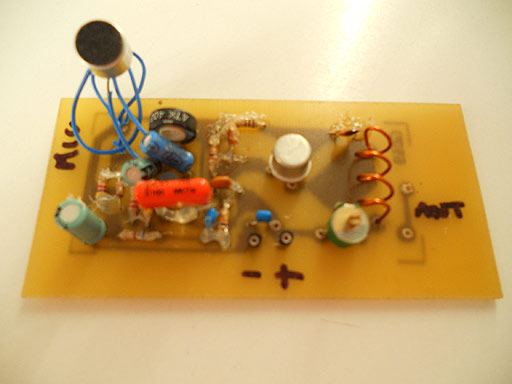
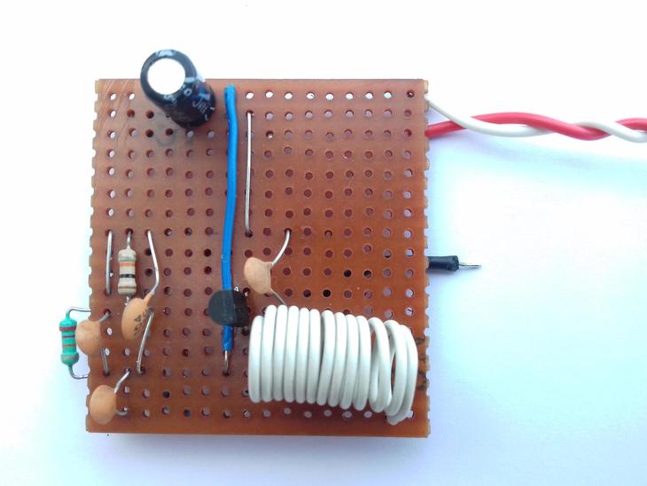
 This FM transmitter circuit is a quite fun project for electronics beginners, so here’s a circuit with the 2SC9018 transistor. It uses the 2SC9018 high frequency transistor, based on a different spin of the common base Collpit’s oscillator. The circuit is rather simple, uses only one transistor and few passive components and performs well in terms of frequency stability, almost zero drifting after about 4 hours of continuous operation.
Posted on Monday, August 7, 2017 • Category: FM Transmitters
Here we are presenting a long range FM transmitter that can cover a reasonable distance of 5 kilometers / 3 miles and beyond with a one watt RF power with full circuit details, bill of material and testing procedure. With 12 volt DC it will deliver 1 watt RF power. With Yagi antenna, looking like early days of TV antenna with aluminum pipes at both at transmitter and receiver end looking each other at line of sight distance, the range can be up to 5 km / 3 miles.
Circuit-Zone.com © 2007-2026. All Rights Reserved.
|