Posted on Monday, May 23, 2011 • Category:
Power Supplies
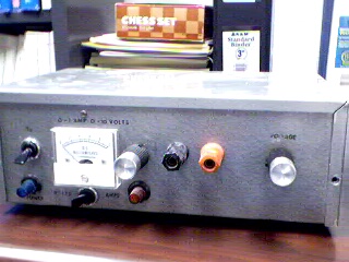
The linear laboratory power supply, shown in the schematic, provides 0-30 volts, at 1 amp current, using a discrete transistor regulator with op-amp feedback to control the output voltage. The supply was constructed in 1975 and has a constant current mode that can be used to recharge batteries. With reference to the schematic, lamp, LP2, is a power-on indicator. The other lamp (lower) lights when the unit reaches its preset current limit. R5, C2, and Q10 (TO-3 case) operate as a capacitor multiplier. The 36 volt zener across C2 limits the maximum supply voltage to the op-amps supply pins. D5, C4, C5, R15, and R16 provide a small amount of negative supply for the op-amps so that the op-amps can operate down to zero volts at the output pins (pins 6). A more modern design might eliminate these 4 components and use a CMOS rail-to-rail op-amp. Current limit is set by R3, D1, R4, R6, Q12, R10, and R13 providing a bias to U2 that partially turns off transistors Q9 and Q11 when the current limit is reached. R4 is a front panel potentiometer that sets the current limit, R22 is a front panel potentiometer that sets the output voltage (0-30 volts), and R11 is an internal trim-pot for calibration. The meter is a 1 milliamp meter with an internal resistance of 40 ohms. Switch S1 determines whether the meter reads 0-30 volts, or 0-1 amp.
 1.2-36V 5A Adjustable Power Supply with LM317 10A 1-30V Variable Power Supply with LM317 Laboratory Power Supply 0-30 Volt LM317 Overvoltage Protection 12V Power Supply - 30A 30V/4A Adjustable Bench Power Supply 5V Power Supply With Overvoltage Protection. 12V 2A Linear Power Supply 12V Dual Power Supply 30V 10A Variable Bench Power Supply
Circuit-Zone.com © 2007-2026. All Rights Reserved.