Circuit-Zone.com - Electronic Projects
Posted on Saturday, May 3, 2008 • Category: Volume Control
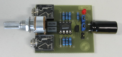
The DS1802 is the dual audio 45kOhm (typically) pot with 65 steps (64x1dB and mute), known around for its possibility to be controlled by its own pushbuttons instead of, usually needed, certain logic circuitry. It is available in DIP package and hence seems very appealing for DIY.
Most of the digital potentiometers (there are exceptions like WM8816 and X9312) can not accept signals much beyond their supply voltages. For DS1802, 0.5V below the potential at its Gnd pin is the bottom, and 0.5V above the Vcc (whose safe maximum is 5.5V above the Gnd pin) is the upper limit. There are a few ways to center the signal inside these boundaries and Dallas recommends Wheatstone Bridge circuit (see App Note 161). I decided to shift the supply rather than signal, thus with one more regulator I could keep the signal path clean. So, DS1802’s Gnd pin went down to -2.5V and all the other pins of DS that normally should go to ground went to this pin: Agnd, Zero-Crossing (enabled) and Mode (stereo), as well as the Up/Down buttons. Resistive networks themselves are connected straightforward. The DS1802’s pin layout appeared almost ideal for such application.
Posted on Sunday, April 27, 2008 • Category: Audio DAC
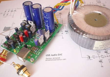 High quality USB Audio DAC with PCM2702. The PCM2702 is a single chip digital-to-analog converter offering two D/A output channels and an integrated USB 1.0 compliant interface controller. The newly developed SpAct™ (Sampling Period Adaptive Controlled Tracking) system recovers a stable, low-jitter clock for internal PLL and DAC operation from the USB interface audio data.
The PCM2702 is based upon Texas Instruments Enhanced Multi-level Delta-Sigma Modulator, an 8x oversampling digital interpolation filter, and an analog output low-pass filter.
The PCM2702 can accept a 48kHz, 44.1kHz and 32kHz sampling rates, using either 16-bit stereo or monaural audio data. Digital attenuation and soft-mute features are included, and are controlled via USB audio class request.
Posted on Thursday, April 24, 2008 • Category: FM Transmitters
 Many people prefer to listen to their own music (or voice) on radio.
This project explain how you can build and connect a powerful 1W amplifier to your FM transmitters.
A perfect solution for those wishing to listen to their favorite tunes in the car, house, garden,
school, campus, party, you name it....
Why not share your music with every one else in your city!
Posted on Thursday, April 24, 2008 • Category: FM Transmitters
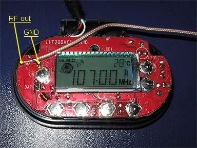
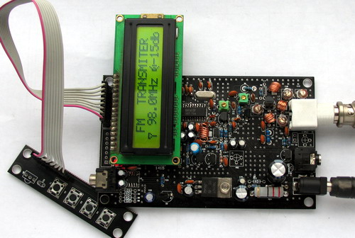 BH1415F FM Stereo PLL Transmitter
Transmitter power amplifier, the output signal from BH1415F by 2 SC9018, 2SC3355, 2SC2053 amplified signal can reach more than 500 mW, adjusting well to achieve greater power. Measured by the pull rod antenna used to be launched in the open 800 meters above. Uses external antenna will be launched even further. attention in 2053 need to be installed and tested at the load connected to leave, or else very easily burn 2053, 50 European amateur production of 2 W can be used instead of resistance. installed and tested at three levels circuit can be installed and tested.
Posted on Thursday, April 24, 2008 • Category: Headphone Amplifiers
 Here is very simple portable hi-fi headphone amplifier built around OPA2132 amplifier chip.
Instead of R5 and R25 is used only wires. These resistors are assembled only in case of oscillation. The value should be few ohms. Now I have to find some good box, and put my CMoy inside. It will be maybe most difficult part of building CMoy amplifier :-).
The sound is very good for so easy and small device. It can improve the sound of MP3 players, mobile phones and other portable devices. I would like to make some measurement of frequency characteristics, THD and also try to use different OpAmps, but unfortunately I don't have enough time to make it now.
Posted on Thursday, April 24, 2008 • Category: AVR
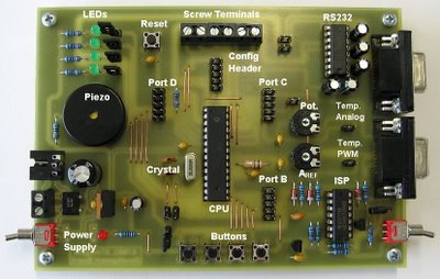 This is versatile development board for AVR microcontrollers ATmega48/88/168. It is good for testing and debugging embedded programs. It has many built-in peripheries connected to microcontroller so you can use them without soldering. ATmega microcontrollers are produced by ATMEL and they include a lot of features: I/O, Timers, PWM generators, ADC, RS232, TWI, SPI, Analog Comparator, Oscillator, EEPROM… These microcontrollers are very versatile, easy to program and easy to use. This is the reason why I like these microcontrollers and why I decided to make development board for them.
Posted on Thursday, April 24, 2008 • Category: USB Soundcards / USB Headphones
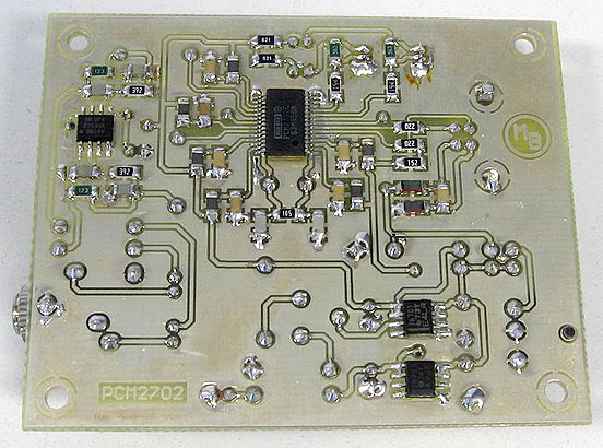 Make a sound card is no more a complex issue. If you use great IC PCM2702 from BURR BROWN / Texas Instruments you can create a fully functional USB sound card. This sound card can be powered from USB port and has one stereo output. You don’t need to install any driver for Windows XP and Vista, because they are already inside. This is really plug and play.
Posted on Wednesday, April 23, 2008 • Category: Amplifiers
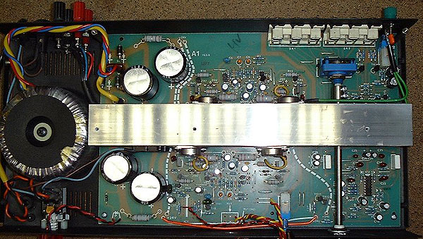 Musical Fidelity would let you believe that this is a Class A design. However, in common with most commercial amplifiers, it is a class AB amplifier - it simply has a rather high standing current in the output stage, which results in the first 8 watts or so being class A.
Posted on Wednesday, April 23, 2008 • Category: FM Transmitters
 A simple FM transmitter links your home-entertainment system to a portable radio that can be carried around the house and into the back yard. For example, you can play music on the CD changer in your living room, and listen to it on a portable radio by the back-yard barbeque.
IC1 is a voltage-controlled oscillator with integrated varactor. Its nominal frequency of oscillation is set by inductor L1, and a 390nH value places that frequency at 100MHz. Potentiometer R1 then lets you select a channel by tuning over the FM band of 88MHz to 108MHz. Output power is about -21dBm into 50 (most countries accept emissions below 10dBm in the FM band).
The home system's left and right audio signals are summed by R3 and R4, and attenuated by the (optional) potentiometer R2. R2's wiper signal serves as a volume control by modulating the RF frequency. Signals above 60mV introduce distortion, so the pot attenuates down from that level.
In the absence of a standard FM radio antenna, 75cm (30 inches) of wire will suffice as a transmitting antenna. For best reception, it should be mounted parallel with the receiving antenna. The IC operates on a single supply voltage in the range 3V to 5V, but you should regulate the applied voltage to minimize frequency drift and noise.
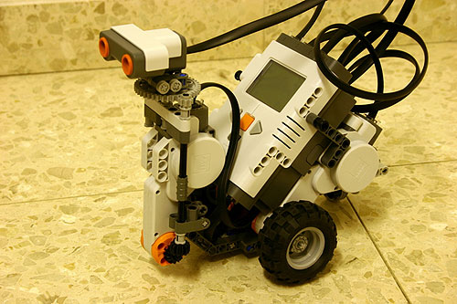
Posted on Tuesday, April 22, 2008 • Category: Robots
The robot is controlled by a NXT-G program that listens to Bluetooth messages that tell it what to do. Normally, the commands are movement commands. These commands control the speed of the robot, whether it will go straight or turn left or right, or whether it will stop. It can also receive a command to do a radar-style scan with the ultrasonic sendor. When it gets such a command, it stops moving, and performs a sequence of ultrasonic measurements while rotating the sensor. It sends these measurements, along with data about what angle the sensor was looking at, back to the PC. When the scan ends, the robot starts responding to movement commands again.
Circuit-Zone.com © 2007-2026. All Rights Reserved.
|