Circuit-Zone.com - Electronic Projects
Posted on Thursday, June 30, 2016 • Category: Frequency Wave Generators
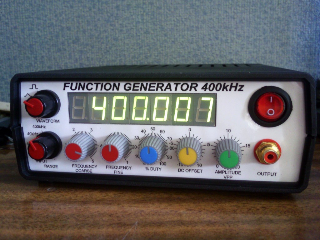
Function generator with adjustable frequency from 0 Hz to over 400 kHz, adjustable amplitude, DC offset, duty, and of course the function selection – square, triangle, and sine. Generator based on good old ICL8038 integrated chip generator that gives pretty good shaped signals as for amateur purposes. This circuit has been designed a little differently than ICL’s note or other similar circuits are suggesting. I tested a bunch of different configurations with different peripherals and chosen the best – so to get good waveshape at 400kHz. I got rid of some of the elements, I added my own solutions. The two ICL chips that i have can oscillate around up to 420-430kHz, and practically we can get good waveforms up to that frequency.
Posted on Sunday, June 28, 2015 • Category: Frequency Wave Generators
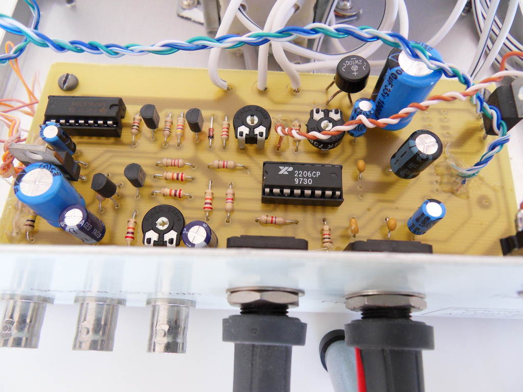 When i was using operational amplifiers at school lab i wanted a function generator at home to play with and work on circuits with Op Amps for better understanding. So i found on the internet a free function generator circuit which uses the IC XR-2206, i printed the PCB with my UV exposure box, i bought an enclosure box, i put everything inside and here is the result. The function generator can generate Square, TTL, Sine and Triangle waveforms from 1Hz to 1Mhz with Voltage regulation to Square Sine and Triangle waveforms.
Posted on Tuesday, April 1, 2014 • Category: Frequency Wave Generators
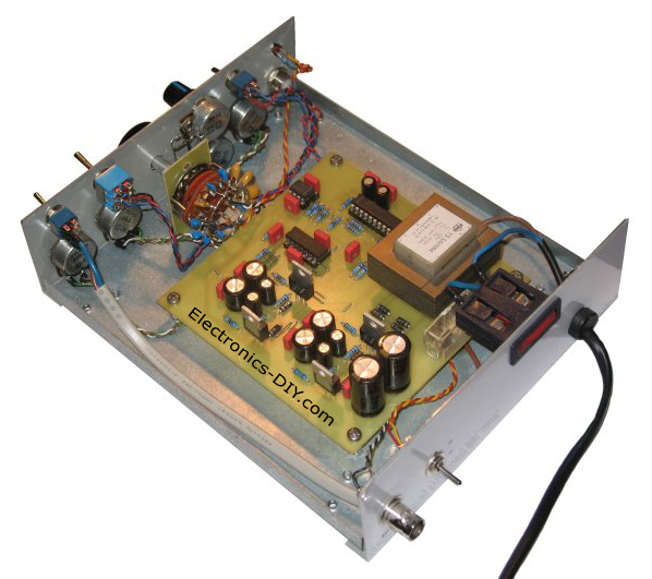 This is simple MAX038 generator. It produces sine, triangle and square waves from 1Hz up to 22MHz. The Amplitude, offset and duty cycle are adjustable to offer wide range of generated signals.
Frequency adjustment is made as a rotary switch S8 with a capacitor bank and variable resistor P7. Amplitude, offset and duty-cycle are performed via variable resistors. Switch S5 selects generated waveform.
Posted on Thursday, April 4, 2013 • Category: Frequency Wave Generators
 Presented here is XR2206 function generator with multiple waveform selection and a frequency readout display. The diagram on the right shows the internal workings of the XR2206 in the form of a block diagram. Essentially the chip contains A VCO (voltage controller oscillator), wave shaper and buffer. The XR2206 frequency generator diagram frequency of the VCO is set with a capacitor and a resistor. The capacitor sets the frequency range whilst a variable resistor can be used to vary the frequency in the set range. The frequency is defined by ƒ = 1/(RC). For a starting point for the design of the frequency generator I used the test circuit from the XR2206 datasheet. I built this on bread board and experimented with the timing resistor and capacitor and managed to get the frequency up to 4MHz.
Posted on Monday, January 17, 2011 • Category: Frequency Wave Generators
 This is a 1Hz - 2MHz XR2206 Function Generator kit that produces high quality sine, square and triangle waveforms of high-stability and accuracy. The output waveforms can be both amplitude and frequency modulated. Coarse frequency adjustment is accomplished using 4-DIP switch for the following four frequency ranges; (1) 1Hz-100Hz, (2) 100Hz-20KHz, (3) 20KHz-1MHz, (4) 150KHz-2MHz. Frequency output can be fine tuned using P1 and P2 potentiometers. The kit includes output that can be connected to 60MHz Counter kit to precisely measure output frequency. 1Hz - 2MHz XR2206 Function Generator kit includes premium quality components, including Audio Grade Gold Capacitors, Gold Plated RCA Connector, WIMA Capacitors, 1% Metal Film Resistors and premium quality PCB with red solder mask and plated through holes.
Posted on Monday, April 12, 2010 • Category: Frequency Wave Generators
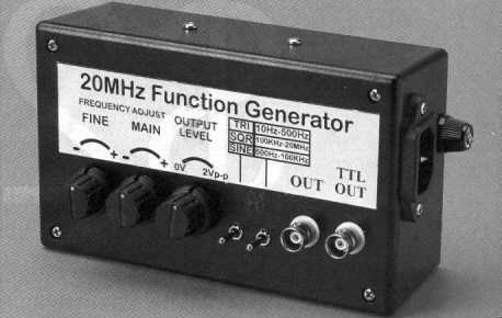 The High Speed Function Generator was published in the professional electronics section of the Aug 1996 issue of Electronics Australia, and has proven to be extremely popular. The kit is no longer available from any of the kit suppliers. The project is capable of generating 20MHz or greater Sine, Square, Triangle, and TTL waveforms.
Posted on Sunday, August 3, 2008 • Category: Frequency Wave Generators
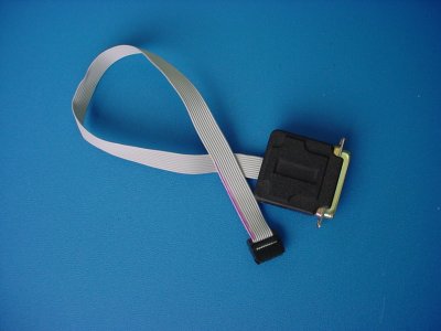
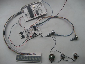
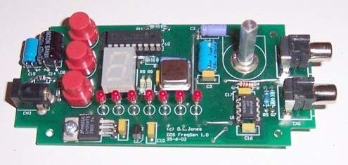 Here is an extremely simple and low cost Sine/Square wave generator based on the Analog Devices AD9835 Direct Digital Synthesis (DDS) Generator chip. The frequency can be set for any frequency from 1Hz to 10MHz in 1Hz resolution steps! All this with three push buttons and a novel “sliding window” LED display. The controller chip is a Microchip PIC16F628.
Posted on Friday, April 11, 2008 • Category: Frequency Wave Generators
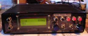 The Max-80 function generator IC is specified to work to 20 MHz. So far, this unit works nicely to 50KHz. Since I seldom need signals higher than that, it has taken up a happy home on my workbench and further development is iffy at best.
There are two basic approaches to controlling the frequency in this type of device. One way is to adjust the voltage to the IC manually and then read out the frequency with a counter. The problem here is you need to fiddle around with the control knob and while waiting for the one-per-second updates on the display.
The other way is to set the display with the control knob and then have the circuit diddle the control voltage to the IC until it settles on that frequency. This is done by calculating the period for the target frequency and then using the PIC to read the pulse width. It then sends short correction pulses to an integrator which controls the IC.
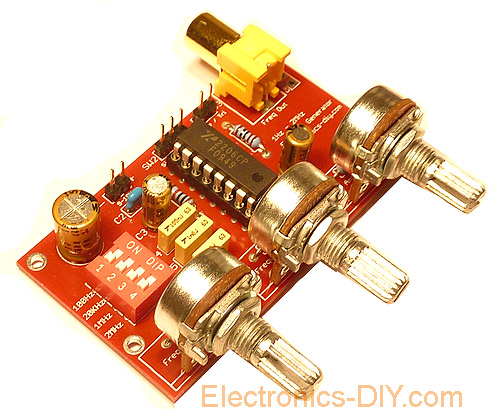
Posted on Thursday, April 10, 2008 • Category: Frequency Wave Generators
 Frequency Generator is an essential laboratory equipment for every electronic. It allows a variety of measurements and experiments. The module described here is based on high quality XR2206 IC and is extremely compact and inexpensive. Output frequency is from 1Hz to 1MHz. It provides sine, square and triangle waves around 1Hz to 1MHz, depending on the timing capacitors used. Over two Potentiometers the amplitude and frequency can be set. About trimmers can also have the purity of the sine signal and the offset of the output voltage can be changed.
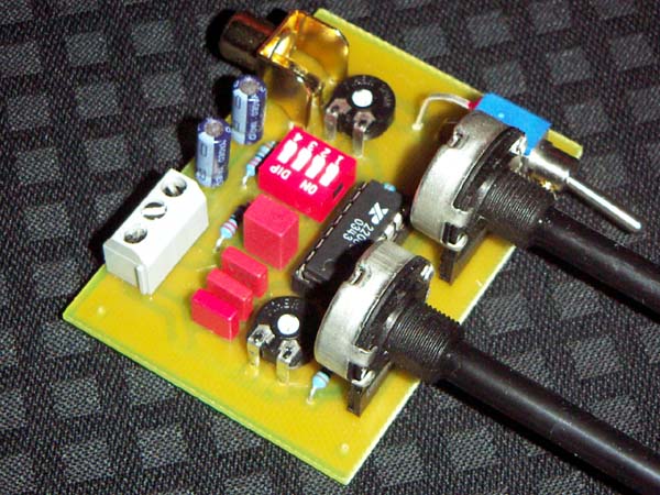
Posted on Tuesday, April 1, 2008 • Category: Frequency Wave Generators
Here's a universal 555 frequency generator with four frequency ranges that might be handy for building any projects that deal with frequencies. JP3 is a button used to switch the device on and off. The power supply (anything from 4-12V) is connected onto JP4. JP2 serves as the output for the signal with an attenuator, if we don't need the full strength (voltage) of the signal, only, say 3V of 5V. We can set the output value by R2. JP1 gives the full strength of the signal, with a current depending on the 555 type you use. R3 is used to set the frequency within a range chosen by the DIP switch S1. You can set which range of frequencies you want to use with a DIP switch. With it you enable or disable a capacitor which is hooked up into the datasheet circuit of the 555 chip.
Circuit-Zone.com © 2007-2026. All Rights Reserved.
|