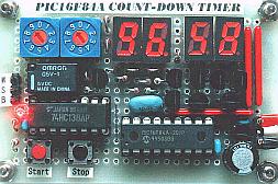
Here is a 60 minute countdown timer that can be used as an exposure timer for UV light boxes, photography, egg timer, and many other projects where counting or delay is necessary. The heart of the countdown timer is PIC16F84A chip and 4 digit character LED display. The relay is energized after the count down timer goes down from specified minute and second until zero, and can both turn devices on or off. See the link for details and schematic.
Posted on Friday, April 11, 2008 • Category:
Timer Circuits
A small circuit that can find a lot applications of measurement time. She has the possibility us inform with sound signal from the BZ1. At the same time, exist the possibility drive a external circuit via the optocoupler IC2, after we connect the applicable circuit in contacts [ A ] and [ B ]. The circuit is based on IC1 (4060), which include in his inside, oscillator and a binary divider of 14 stage. The frequency operation of oscillator is determined by a circuit R-C that connected in pins 9,10,11 of IC1. We give supply in the circuit, with switch S1, is presented a pulse in 12 [ RESET ] via C1 and R3, null him counter, require the measurement of pulses to begin from the zero. Than the count get at in 14th digit then exit Q14 in the pin 3, acquire high logic level. This voltage drive the base the Q1-2, the transistors turn on, thus buzzer BZ1 sound, also the IC2 is ready to drive, via contacts [ A][B ], any suitable external circuit. The time delay is regulated with the potentiometer RV1, in time delay that begin from 1 minute up to 2 hours, proportionally with the combination of prices that they will have the RV1 and C2.
Circuit-Zone.com © 2007-2026. All Rights Reserved.