Circuit-Zone.com - Electronic Projects
Posted on Wednesday, November 16, 2016 • Category: Test and Measurement
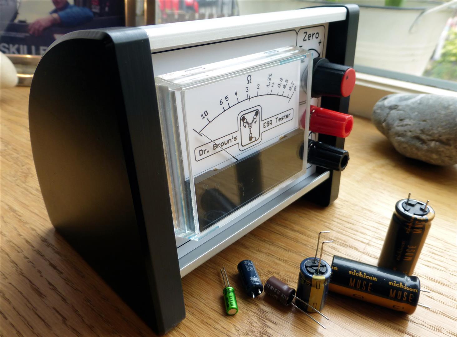
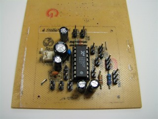
I finally got round to making my capacitor ESR tester this week after finding a nice simple 5 transistor version. Unfortunately, for me, the design was only SMD so, I decided to replicate his schematic in Eagle PCB using a through hole component design. I will not be going into much detail regarding ESR or Equivalent Series Resistance Meters as, there is already plenty of other sources of information on the subject. Yet, every tinkering knows capacitors are guilty of a lot of sins in electronics. Capacitors love to throw red herrings! They can appear physically fine (no bulge), show good capacitance and hide in circuit, standing to attention like the Queens Guards hiding shorts and high resistance under their big hats. This is where the ESR tester can be a saviour, with the ability to test for "out of specification" high resistance, within the capacitor. They can also be used to test "in circuit", without the need to remove every capacitor in the circuit.
Posted on Monday, July 28, 2014 • Category: Test and Measurement
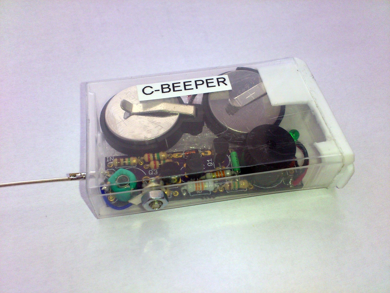 Curious C-Beeper is a fun to build little probe that can be used to quickly detect the capacity of capacitors in pF nF range, test their stability with temperature changes, find broken wires, locate wires, trace wires on PCBs, and to locate live wires behind the walls without touching them. The circuit uses three transistors to make a most unusual capacitance beeper probe. When a capacitor is touched to the probe, the probe beeps at a frequency that varies with capacitance. The frequency change is so steep with capacitance that tiny capacitors may be precisely matched or an exact fixed value may be selected to replace a trimmer in a prototype. If the user has reasonably moist skin, simply holding one lead of the capacitor to be tested while touching the other lead to the probe is all that is necessary. The user's body forms the other connection through the beeper's metal case. When the beeper is properly adjusted it draws only 10 uA with nothing touching the probe - no power switch is required. This design is optimized for capacitors less than about 0.1 uF (100 nF). Large capacitors give a low frequency "clicking" sound and small capacitors sound a tone that increases as the capacitance decreases. Many decades of frequency change occur over the beeper's range giving even the more tone-deaf among us sufficient change to discern slight differences in capacitance. The entire device is powered by two CR2032 lithium cells that fit into TicTac box. The use of power switch is unnecessary since the circuit consumes almost no power when not being used.
Posted on Sunday, March 9, 2014 • Category: Test and Measurement
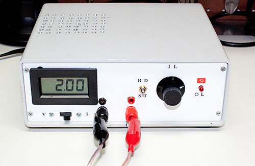 An adjustable power load is a piece of test equipment that often comes handy in the development of a certain electronics projects. For example, when you are building a power supply, it will come a time when you need to "simulate" a load to see how well your design performs as the load varies. Adding power resistors to the output can sometimes do in a pinch, but often you will not have the right resistor value handy with the right power rating for the test. This is where an adjustable electronic load comes handy. In this article, I'll show how you can build one using common components available to the electronics hobbyist.
Posted on Monday, May 6, 2013 • Category: Test and Measurement
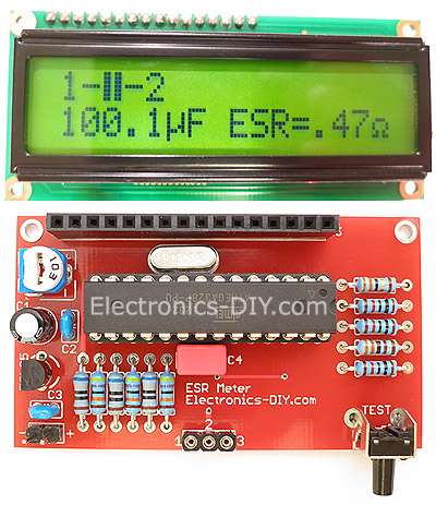 ESR Meter is an irreplaceable tool for troubleshooting and repairing electronic equipment by determining performance and health of electrolytic capacitors. Unlike other ESR Meters that only measure ESR value this one measures capacitor's ESR value as well as its capacitance all at the same time. Additionally, ESR Meter also tests and identifies PINs of all transistors such as Bipolar (NPN, PNP), FETs, MOSFETs (N-Channel, P-Channel, enhancement-mode and depletion-mode MOSFETs), Thyristors, SCRs and Triacs. Tests and identifies PINs and voltage of diodes, dual diodes, varicap diodes (and their capacity), zener diodes (test voltage up to 5V) and LEDs. It measures resistance of resistors, power resistors, coils starting from just 0.1Ω up to 20MΩ.
Posted on Tuesday, January 29, 2013 • Category: Test and Measurement
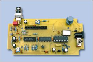
 This is high quality function generator system using the XR2206 chip. Waveform function generator capable of producing AM/FM modulated sine wave outputs find a wide range of applications in electrical measurement and laboratory instrumentation. This application note describes the design, construction and the performance of such a complete function generator system suitable for laboratory usage or hobbyist applications. The entire function generator is comprised of a single XR2206 monolithic IC and a limited number of passive circuit components. It provides the engineer, student, or hobbyist with highly versatile laboratory instrument for waveform generation at a very small fraction of the cost of conventional function generators available today.
Posted on Friday, November 30, 2012 • Category: Test and Measurement
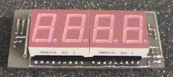
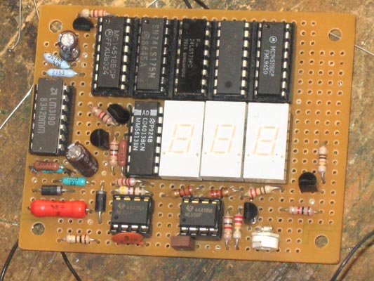
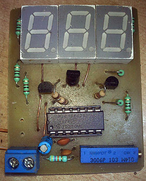 This is a simple 30V volt meter using PIC16F676 micro controller with 10-bit ADC (analog to digital converter) and three 7 segment LED displays. You can use this circuit to measure up to 30V DC. The possible applications are on bench power supply or as a digital panel meter in various systems. PIC16F676 is the heart and brain of this circuit. The internal adc of the mcu with a resistor network voltage divider is used to measure the input voltage. Then 3 digits of comm anode 7 segment display is used to display final converted voltage. As you can see in the schematic the displays are multiplexed with each other. It means we switch on one display and put the corresponding digit on this while other two displays are off this cycle goes for each of the displays.
Posted on Tuesday, October 16, 2012 • Category: Test and Measurement
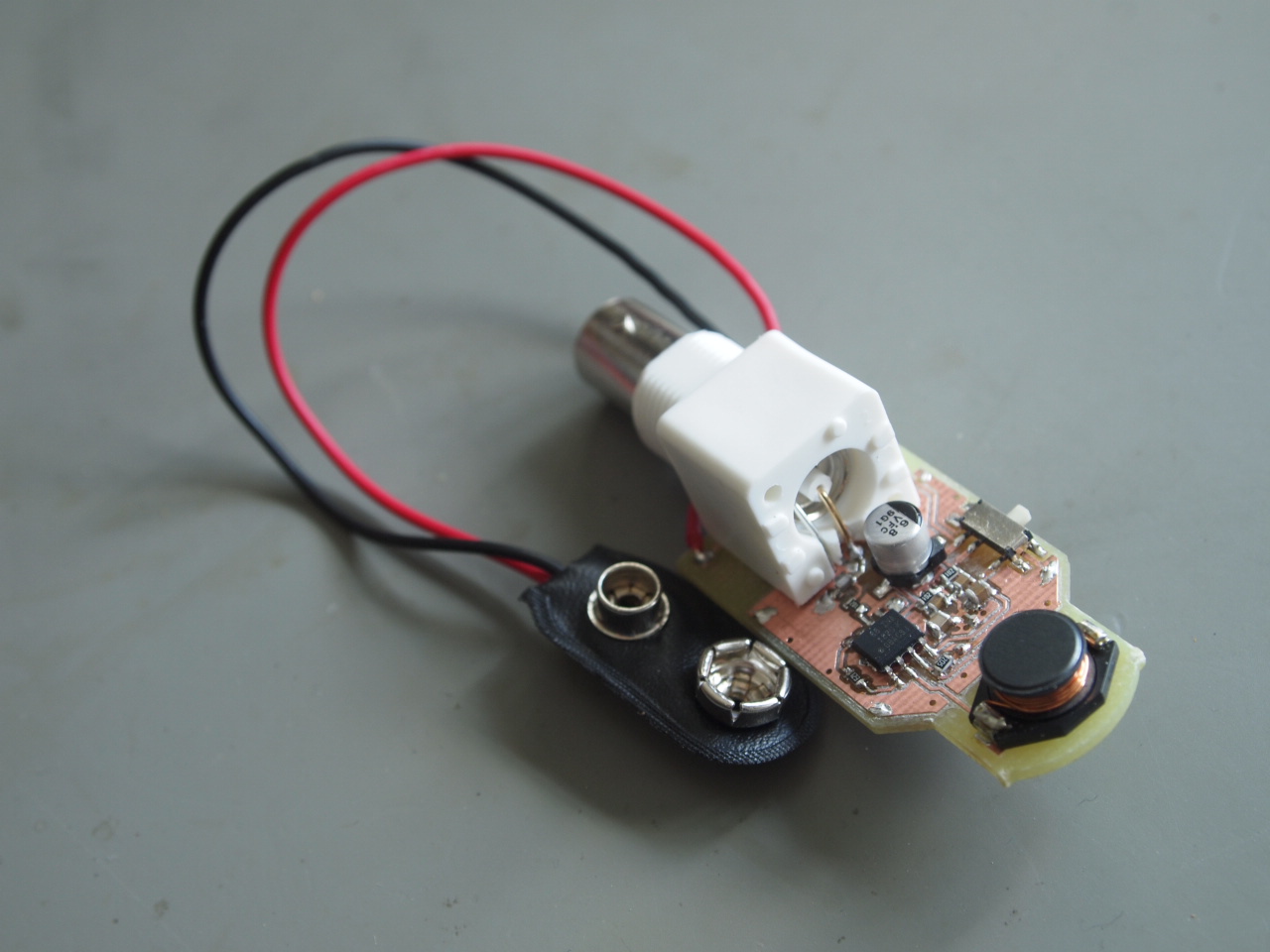 There's something fascinating about electromagnetic fields. Thanks to the modern world and the prevalence of electronics and electricity, they're all around us these days. But because of the extremely limited array of senses that we humans have, we spend most of the time completely oblivious of them. Wouldn't it be cool to make something simple that could not just detect them, but would allow you look at the waveforms on an oscilloscope. An EMF probe in other words.
Posted on Wednesday, May 23, 2012 • Category: Test and Measurement
 Field strength meter is extremely useful when working with RF devices. It can be used to quickly diagnose whether a transmitter circuit is working, and can be used to detect RF signals in the environment. The simplest field strength meter could be built with a tuned LC circuit and a germanium diode, just like the way of a building a crystal radio except replacing the ear piece with a high sensitivity current meter. While this approach fits the needs of most simple applications, it has a pretty narrow frequency range (~100 MHz) and requires tuning the LC circuit to the correct frequency before measurements can be made and the design can become complicated if wider frequency range tuning is desired.
Posted on Friday, March 23, 2012 • Category: Test and Measurement
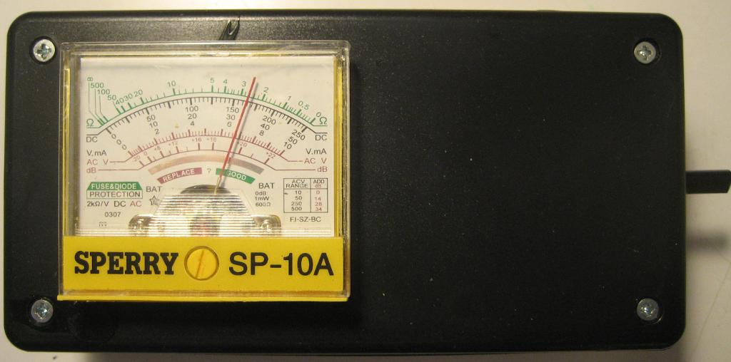
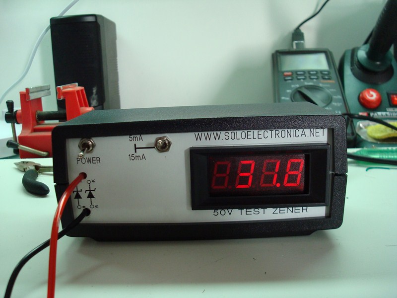 Presented here is zener diode meter for testing voltage value of an unknown zener diode. The zener diode or diode voltage regulator is a special diode, Unlike normal diodes these diodes are intended to work in the breakdown voltage and an essential part of the voltage regulator circuits.
These components maintain constant voltage at its terminals suffer variations even when substantial current, its connection with reverse bias is normal also to work in the zener voltage of the source Vs must be greater than the rupture Vz, as always condition using a resistance Rs in series to limit current to a value always less than its maximum power.
Posted on Tuesday, January 3, 2012 • Category: Test and Measurement
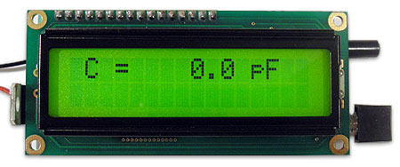
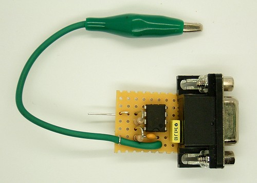 RF laboratory often requires capacitance meter for small capacitors in pF range. Such a device can easily be built by yourself. Here, a measurement converter for PC serial port is presented. The frequency of an oscillator is reduced by the target and measured on a PC. The appropriate conversion then allows the direct display of the capacity. The input uses a short and low capacitance probe tip. The opposite pole is clamped to ground cable with a crocodile.
The NE555 precision timer receives its operating voltage directly from the serial interface and produces a measurement object without C is a square wave with a frequency of 3.5 kHz. The signal is processed via the CTS input of the interface.
Posted on Saturday, December 31, 2011 • Category: Test and Measurement
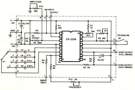
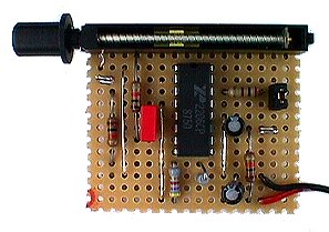 For measurement purposes in the electronics laboratory is needed again and again signals of different frequency and waveforms. A common function generator provides sine, for example, triangular and square waves. The frequency must be adjustable and at least cover the low frequency range.
The low-cost IC XR2206 provides a very simple function generator with only a few external components. XR2206 data sheet provides complete basic circuit for a simple function generator. It requires an operating voltage of 12 V and delivers sine and square wave signals. Instead of the sine wave output is obtained after opening of S1 a triangular output wave. XR2206 IC contains an internal VCO (Voltage Controlled Oscillator, Voltage Controlled Oscillator) with triangular and rectangular output. The capacitor C and the power to determine the frequency at pin 7. With a pot of 2 megohms and a fixed resistor of 1 kOhm variation gives a ratio of 1 to 2000 and may include a range of 10 Hz to 20 kHz sweep.
Posted on Sunday, September 11, 2011 • Category: Test and Measurement
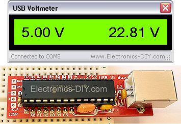 USB Voltmeter is a PC based dual channel voltmeter built around PIC18F2455 / PIC18F2550 microcontroller that measures voltage from 0.00V up to 500.00V with 10mV resolution. USB Voltmeter sends measured data to PC via standard USB connection displaying data on a computer monitor. USB Voltmeter is self-powered drawing very little current from USB port. Voltage readings are displayed via included USB Voltmeter software.
Posted on Wednesday, August 10, 2011 • Category: Test and Measurement
 Even if the digital multimeter have dominated in a lot of applications, in the measurement, exist the need for existence of instruments of clue in various appliances, voltage and current, as in power supply or elsewhere. The circuits that give make this precisely the work, measure the voltage in terminal a circuit and the current that passes in his. The circuit does not present particular difficulties for somebody that has a small experience. The two circuits are the himself, with a small difference only in their input, when they have they measure voltage or current and in connection that concern decimal point [ dp ]. In the department of input IC1 and IC3, exist the CA3161E, that is a A/D Converter for 3-Digit Display. In the drive of Display IC2 and IC4, exist CA3161E, that is a BCD the Seven Segment Decoder/ Driver. As it appear in Fig.1, that concern the voltmeter in input [ + IN ], exist in series a what resistor R1 in combination with the R3 create a voltage divider. On the contrary in the Fig.2 that it concern the ampere meter, this resistor does not exist, because the circuit is connected differently, thus the current pass through the R5, creating a fall of voltage, in her terminal, proportional current that it pass from this.
Posted on Saturday, August 6, 2011 • Category: Test and Measurement
 I wanted a digital AC voltmeter to measure the output range from 0 to 150VAC with reasonable accuracy. Sure I could buy some premade DVM packages or use a microcontroller with a built-in ADC, but I wanted to make one from scratch myself using readily available parts I had on hand. I aimed for reasonable accuracy so I chose to have a 2 and a half display for the voltage, meaning the meter reads from 000 to 199. Below is the schematic of the AC DVM.
Posted on Wednesday, August 3, 2011 • Category: Test and Measurement
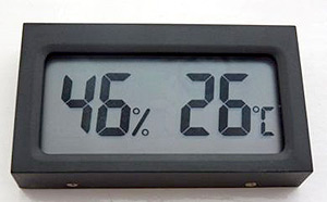 Here's hygrometer thermometer that simultaneously monitors both humidity and temperature on large LCD display which can be read from across the room. It's great for labs, chemical storage areas, clean rooms, stock rooms, warehouses, factories, greenhouses, and outdoors. Monitor humidity and temperature in your room, kitchen, desiccators, incubators, refrigerators, and fume hoods. Comes with AG13/LR44 battery. Temperature range -10 C to 50 C (14 F to 122 F). Humidity range 20% RH to 95% RH.
Posted on Wednesday, July 13, 2011 • Category: Test and Measurement
 Here is a very simple circuit that can b e used to check the hfe of transistors. Both PNP and NPN transistors can be checked using this circuit. Hfe as high as 1000 can be measured by using this circuit.The circuit is based on two constant current sources build around transistors Q1 and Q2.The Q1 is a PNP transistor and the constant current flows in the emitter lead. The value of constant current can be given by the equation; (V D1 -0.6)/ (R2+R4).The POT R4 can be adjusted to get a constant current of 10uA.
Posted on Tuesday, July 5, 2011 • Category: Test and Measurement
 This RF inductance meter measures RF chokes in the 500 nH to 50 uH range. I needed a way to measure hand-wound RF inductors in my second lab, and since I would only be doing this occasionally, I didn't need anything fancy, and since once a friend finishes his AT90S1200-based design, I plan to make one myself, I figured I'd use this for less than a year, so I didn't want to invest a lot of time in making it . I had run across the forerunner of this circuit, one that is more sophisticated in that it has a zero adjustment and range switch, but it was limited to higher inductances. I adapted it to the components I had on hand and changed it so that it would work in the 500 nanohenry to 50 microhenry range.The original circuit was reportedly published a few years ago by the Amrican Radio Relay League, so it is with appreciation of the ARRL that I make this circuit available.
Posted on Saturday, July 2, 2011 • Category: Test and Measurement
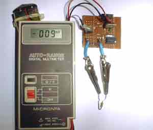
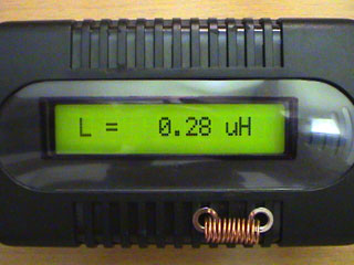
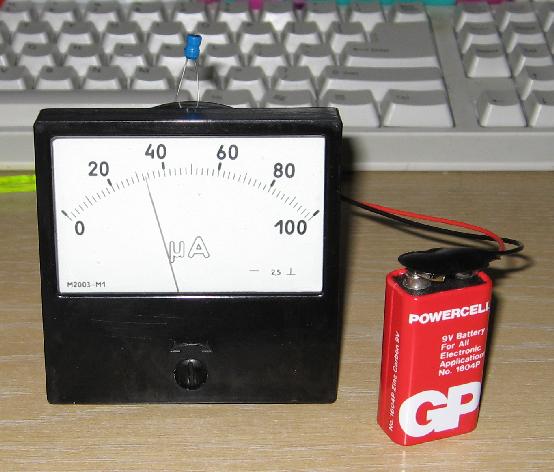 This is inductance meter I built using 74HC14 IC. Initially I used a DMM as the display device, but on a whim I tried hooking up a moving-coil meter. To my surprise, it actually worked just fine, 1K in series was sufficient to allow a useful calibration and didn't overload the drive capabilities of the last gate in the package.
I calibrated my unit for 0-100 uH, as this is the range I am generally most interested in, and it gives direct-readings on the uA scale of the meter. With the values as Dick specified, there is sufficient range to calibrate it from about 25 uH to 250 uH FSD.
Posted on Saturday, May 28, 2011 • Category: Test and Measurement
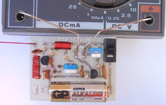 This Field Strength Meter has been specially designed for our FM bugs. It is capable of detecting very low power transmitters and will assist enormously in peaking many of our FM transmitters that have a coil in the output stage that can be adjusted for optimum output.
Up to now, field strength meters have only been able to detect transmitters with an output of 100 milliwatts or higher, and for an output such as this, a simple circuit such as a meter and a coil is sufficient. But when it comes to a low power device, a simple circuit, with no amplification, is not suitable.
We spent more than 5 days building all the circuits we could find - that purported to be suitable for low-power transmitters, hoping to find one that would work.
Unfortunately none came anywhere near good enough so we had to design our own.
The circuit we came up with is shown above and it incorporates an RF amplifier, diode rectification, and a DC amplifier so that a movement from a multimeter (a movement is the 'meter' part of a multimeter) could be used as the readout. The heart of the design is a pair of diodes that are partially turned on via a resistor (the 100k sensitivity control) and this overcomes some of the .6v threshold of a diode.
You may not think .6v is very much but when you are talking in millivolt terms, it is 600 millivolts. The signal we are attempting to pick up produces one or two millivolts on the receiving antenna and if you need 600 millivolts to turn a diode ON, the field strength meter becomes very insensitive.
Posted on Wednesday, May 18, 2011 • Category: Test and Measurement
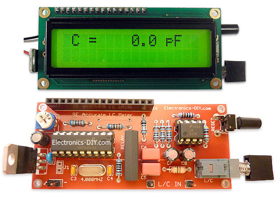 Build your own Special Edition Accurate LC Meter (Inductance Meter / Capacitance Meter) and start making custom made precision coils and inductors. Accurate LC Meter allows to measure incredibly small inductance making it perfect tool for making all types of RF coils and inductors. It can measure inductance starting from only 10nH - 1000nH, 1uH - 1000uH, 1mH up to 100mH and capacitance from 0.1pF up to 900nF.
Special Edition LC Meter includes top notch high precision components that are only found in premium quality kits. It includes high quality double-sided printed circuit board (PCB) with red solder mask and pre-soldered tracks for easier soldering, detachable LCD display with yellow-green LED backlight, programmed PIC16F628A microcontroller chip, high precision capacitors and inductor, 1% Metal Film resistors, Machined IC Sockets, gold plated header pins, LCD header connectors and all the other components that are needed to build a premium quality kit. Thanks to the use of LCD connectors LCD display can be detached from the main PCB board at any time even after the kit has been assembled. All components are through-hole and are easy to solder. Special Edition Accurate LC Meter is designed for professionals that require unprecedented measurement accuracy and offers great value at low cost.
Posted on Tuesday, May 17, 2011 • Category: Test and Measurement
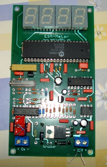 This ESR Meter is perfect for any electronics repair technicians, engineers or hobbyist. This handy ESR meter measures electrolytic capacitor equivalent series resistance (ESR) in the circuit. ESR is a very important characteristic of capacitors greater than 1 microfarad. This meter makes measurements which are often impossible to check with standard digital capacitance meters. This ESR meter is based around ICL7107, 4049, NE555 and TLC274 operational amplifier and can measure resistance from 0.01 Ohm up to 19.99 Ohm. ESR value is displayed in Ohm on four digit LED display . The power consumption is only 8mA using 12V battery. ESR Meter offers very simple design and is easy to assemble.
Posted on Tuesday, May 10, 2011 • Category: Test and Measurement
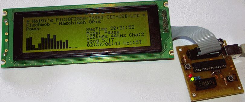 This is PIC18F2550 based Spectrum analyzer mod for PC. It uses WG24064A 240x64 graphical LCD with T6963 controller to display the result.
Posted on Friday, May 6, 2011 • Category: Test and Measurement
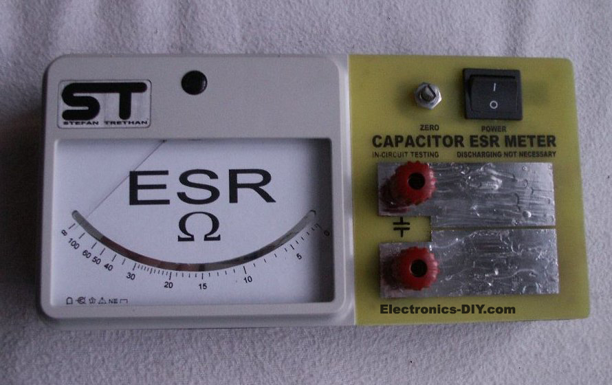
 "ESR" stands for equivalent series resistance. ESR is one of the characteristics that defines the performance of an electrolytic capacitor. Low ESR is highly desirable in a capacitor as any ripple current through the capacitor causes the capacitor to heat up due to the resistive loses. This heating accelerates the demise of the capacitor by drying out the electrolyte at an ever increasing rate. Over the lifetime of a capacitor, it is not uncommon for the ESR to increase by a factor of 10 to 30 times or even go open circuit. Typical lifetime ratings for electrolytics are 2000-15000 hours and are very dependant on ambient operating temperature. As the ESR increases, the filtering operation of the capacitor becomes impaired and eventually the circuit fails to operate correctly.
Why are ESR Meters so Useful?
A typical capacitor checker measures the capacity (usually in micro farads) of the test capacitor. Some advanced units also test for leakage current. Most of these testers require that the capacitor be removed from the circuit. Unless the capacitor has totally failed, they will not detect a high ESR value. In a typical circuit, there may be 10's or 100's of capacitors. Having to remove each one for testing is very tedious and there is a great risk of damaging circuit boards. This tester uses a low voltage ( 250mv ) high frequency (150khz) A/C current to read the ESR of a capacitor in the circuit. The in circuit testing is possible because of the low voltage used for obtaining the measurement. The voltage is low enough that solid state devices in the surrounding circuitry are not activated and do not affect the low resistance reading we are attempting to obtain. A lot of capacitor checkers will be damaged if you happen to test a charged capacitor. This circuit is A/C coupled and will withstand up to 400vdc of charge on a capacitor (but watch your fingers!). The ESR checker will not detect shorted capacitors as they will read with a very low ESR value. If you are trouble shooting a circuit, you will have to use several instruments including your nose, voltmeter and oscilloscope to locate all the possible failure modes. My experience has found that the ESR meter catches about 95% of capacitor problems and potential problems.
Posted on Monday, May 2, 2011 • Category: Test and Measurement
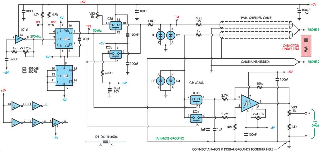 As electrolytic capacitors age, their internal resistance, also known as "equivalent series resistance" (ESR), gradually increases. This can eventually lead to equipment failure. Using this design, you can measure the ESR of suspect capacitors as well as other small resistances. Basically, the circuit generates a low-voltage 100kHz test signal, which is applied to the capacitor via a pair of probes. An op amp then amplifies the voltage dropped across the capacitor’s series resistance and this can be displayed on a standard multimeter. In more detail, inverter IC1d is configured as a 200kHz oscillator.
Its output drives a 4027 J-K flipflop, which divides the oscillator signal in half to ensure an equal mark/space ratio. Two elements of a 4066 quad bilateral switch (IC3c & IC3d) are alternately switched on by the complementary outputs of the J-K flipflop. One switch input (pin 11) is connected to +5V, whereas the other (pin 8) is connected to -5V. The outputs (pins 9 & 10) of these two switches are connected together, with the result being a ±5V 100kHz square wave. Series resistance is included to current-limit the signal before it is applied to the capacitor under test via a pair of test probes. Diodes D1 and D2 limit the signal swing and protect the 4066 outputs in case the capacitor is charged.
Posted on Thursday, April 28, 2011 • Category: Test and Measurement
 LM386 audio probe amplifier is an essential tool for troubleshooting audio stages in audio related circuits such as amplifiers, oscillators, function generators, phone circuits, radios and lots of our other projects. It is a very handy piece of test equipment that can be built on pre-drilled board and will make a perfect addition to your electronic collection. There are lots of things that can go wrong with an audio stage. It can produce distortion or a “hollow” sound, go weak or simply fail altogether.
Likewise tone circuits can present a number of faults and it is very handy to be able to “hear” what is going wrong.
It is not sufficient to measure the DC voltages on these stages. This only gives a partial picture of the conditions and does not tell you the quality of the audio being processed. To determine this you need a piece of test equipment that will let you see or hear what is being processed. Some of the projects you can test with the Mini Bench Amplifier are tone circuits while others are audio circuits. Tone circuits and audio stages are surprisingly difficult to test unless you have an audio probe or a oscilloscope. Oscilloscope is an ideal piece of equipment but if your budget does not extend this far, the next best thing is an audio probe.
Posted on Thursday, April 21, 2011 • Category: Test and Measurement
 The generator was build using XR-2206 function generator IC, which is capable to generate sine, square, ramp and pulse waveforms in frequency range of 0.01Hz to 1MHz. The amplitude and frequency is modulated by voltage (potentiometers). The example circuit from datasheet worked well.
Posted on Friday, March 25, 2011 • Category: Test and Measurement
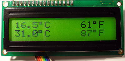
 DS18S20 dual temperature meter uses two very exciting DS18S20 digital temperature sensors that come in convenient TO92 package. Unlike regular sensors where temperature readings are passed as varying voltage, DS18S20 passes temperature information in a digital format as data. This brings many new possibilities and enables to pass temperature information over much longer distances just over a two wire cable. With this capability temperature can be measured in different locations at the same time away from the main circuit board. With regular temperature sensors that rely on the voltage cables must be as short as possible because longer wire lengths introduce stray resistance and bring unreliable readings. Another great feature of DS18S20 sensor is that it doesn't require any calibration at all, while providing 100% accuracy out of the box. That means that you just plug it in and there's no need spending time recalibrating temperature readings. This is all due thanks to the nature of sending information in a digital format. In fact DS18S20 is just like a computer connected to the network that has a unique serial number identifier similar to an IP address. Multiple DS18S20 sensors can send information simultaneously, even over the same two wire bus cable. The two wires provide 3-5V voltage supply to the sensors and they are also used to pass data in two different directions. If wires are very long so that voltage on DS18S20 sensors drops below 3V external 5V voltage supply can be used with 1K resistor to power the sensors.
Once PIC microcontroller receives temperature information it converts it into both Celsius and Fahrenheit values so that they can be displayed on LCD display. DS18S20 dual temperature meter is capable of measuring temperatures from -55 to 125 °C degrees Celsius (-67 to 257 °F Fahrenheit) with 0.5 °C / 1 °F accuracy. If you just need to measure temperature in one location you may just use one DS18S20 sensor and PIC16F628 microcontroller will use just one sensor.
Posted on Thursday, March 24, 2011 • Category: Test and Measurement
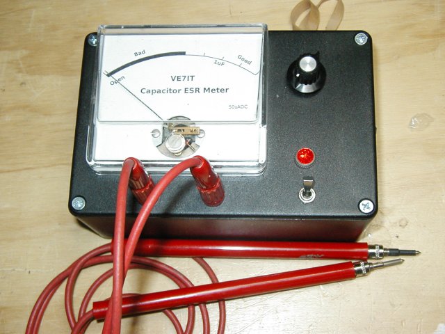
 The ESR Meter is basically an AC Ohmmeter with special scales and protective circuitry. It provides a continuous reading of series resistance in electrolytic capacitors. It operates at 100 kHz to keep the capacitive reactance factor near zero. The remaining series resistance is due to the electrolyte between the capacitor plates and indicates the state of dryness. Capacitor termination problems also show up plainly due to the continuous ohmic reading. The ESR meter uses 8 operational amplifiers. An op-amp is an idealized basic amplifier with two inputs. The non-inverting input (+) has an in-phase relationship with the op-amp output, and the inverting input (-) an out-of-phase relationship. Op-amps are usually used with negative feedback and reach a stable operating condition when their two inputs are equal in voltage.
Op-amps IA & 1B form a regenerative 100 kHz oscillator circuit. Capacitor C1 is the basic timing capacitor and RI is selected to set frequency. Diodes D2 & D3 clip the bottom and top of the output waveform so that the output level and frequency are resistant to battery voltage changes.
Posted on Friday, January 21, 2011 • Category: Test and Measurement
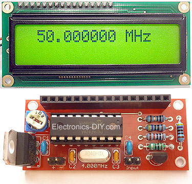 This is 60 MHz frequency meter / counter for measuring frequency from 10 Hz to 60 MHz with 10 Hz resolution. It is a very useful bench test equipment for testing and finding out the frequency of various devices with unknown frequency such as oscillators, radio receivers, transmitters, function generators, crystals, etc. The meter provides very stable readings and has excellent input sensitivity thanks to onboard amplifier and TTL converter, so it can even measure weak signals from crystal oscillators. With the addition of prescaller it is possible to measure the frequency of 1GHz and above. The meter measuring range has been recently upgraded and it can now measure from 10Hz to 60MHz instead of 10Hz to 50MHz.
Posted on Monday, January 17, 2011 • Category: Test and Measurement
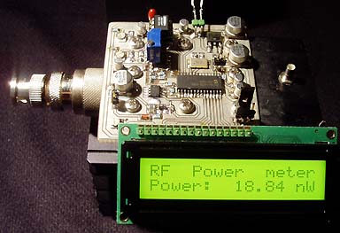
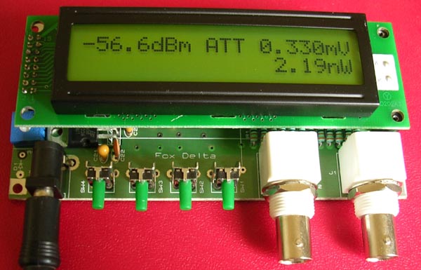
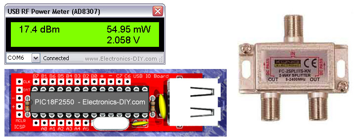 Measurement of transmitter output RF power has never been easier and more precise. AD8307 USB 0-500MHz RF Power Meter allows to measure the power of transmitters from 1nW to 2W. Output is displayed in dBm, Watts (nW, uW, mW and W range) as well as input voltage. USB RF Power Meter is based on popular AD8307 watt meter IC and PIC18F2550 microcontroller. Instead of using LCD display module the meter connects to a PC via USB port and displays measurements on a computer via USB RF Power Meter software. The software settings can be changed to use 10-50dBm attenuator and thus allowing to measure higher RF power than 2W.
Posted on Wednesday, January 12, 2011 • Category: Test and Measurement
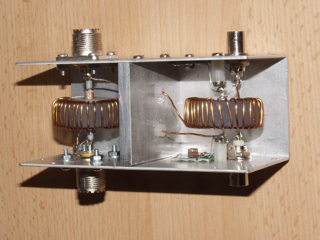 A pair of AD8307 RSSI (Received Signal Strength Indicator) chips are used to produce DC voltages that are proportional to the logarithm of the Forward and Reflected power levels. These DC voltages can then be subtracted in an Op Amp to produce a voltage proportional to SWR which is essentially independent of power level. The Forward DC voltage also drives a separate Power meter. I have modified Paul's design to use a "Stockton" directional coupler, and to provide a peak-reading capability. The meter automatically provides an accurate readout of SWR for any power level between 10mW and 1000W. I arranged for the Power meter to cover the range 100mW to 1000W, but it is easy to change the circuit to set upper and lower power limits to any values in the range 100uW to 1000W.
Posted on Monday, January 10, 2011 • Category: Test and Measurement
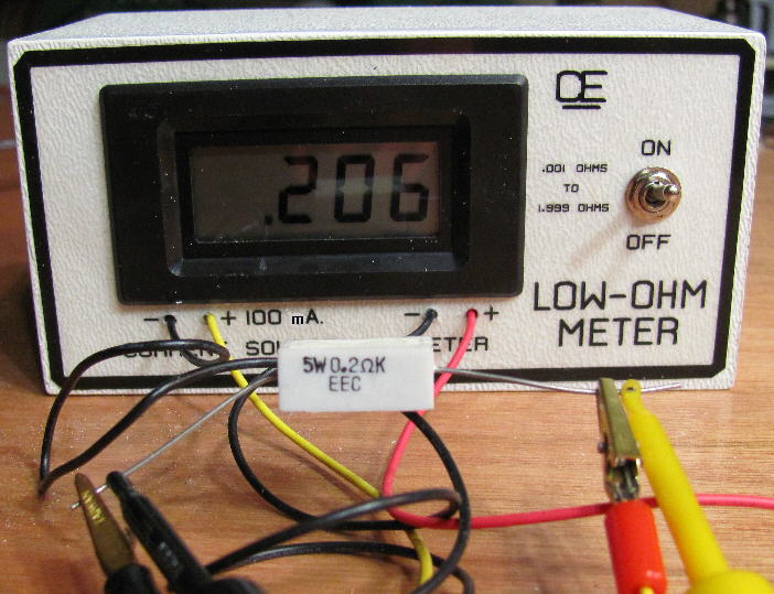 A very simple circuit to measure low resistance values from 0.001 up to 1.999 Ohm. With a "Direct Resistance Readout in Ohms". You must use two separate batteries. One for the DMM and one to supply power to the LM317LZ. I recommend the LM317LZ, which is the 100 mA, T0-92 version of the normal LM317. But you can also use the LM317, in the T0-220 package, if you want. The trimpot must be set precisely to deliver 100.0 mA out to get truly accurate resistance measurements.
So you need a very accurate Milli-Amp Meter to adjust this Correctly.
(And like Any Test Equipment, This Calibration should be Re-Checked once a year or so.)
Posted on Monday, January 10, 2011 • Category: Test and Measurement
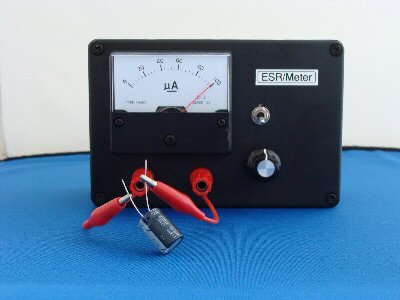
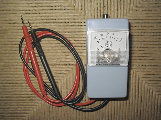
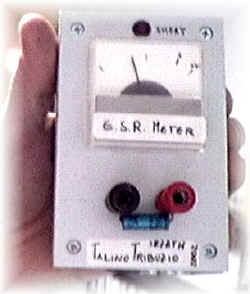 The project came from an Italian magazine Nuova Elettronica N212. It's very simple but interesting ESR Meter. I've built it and tested some capacitors and it's very useful.
It measures the ESR (Equivalent Series Resistance) of capacitor (electrolytic and not) that s used to tell if a capacitor is good or not. ESR Meter uses a bridge circuit that works at 100KHz.
Posted on Sunday, January 9, 2011 • Category: Test and Measurement
 A typical capacitor checker measures the capacity (usually in micro farads) of the test capacitor. Some advanced units also test for leakage current. Most of these testers require that the capacitor be removed from the circuit. Unless the capacitor has totally failed, they will not detect a high ESR value. In a typical circuit, there may be 10's or 100's of capacitors. Having to remove each one for testing is very tedious and there is a great risk of damaging circuit boards. This tester uses a low voltage ( 250mv ) high frequency (150khz) A/C current to read the ESR of a capacitor in the circuit. The in circuit testing is possible because of the low voltage used for obtaining the measurement. The voltage is low enough that solid state devices in the surrounding circuitry are not activated and do not affect the low resistance reading we are attempting to obtain. A lot of capacitor checkers will be damaged if you happen to test a charged capacitor. This circuit is A/C coupled and will withstand up to 400vdc of charge on a capacitor (but watch your fingers!). The ESR checker will not detect shorted capacitors as they will read with a very low ESR value. If you are trouble shooting a circuit, you will have to use several instruments including your nose, voltmeter and oscilloscope to locate all the possible failure modes. My experience has found that the ESR meter catches about 95% of capacitor problems and potential problems.
Posted on Sunday, January 9, 2011 • Category: Test and Measurement
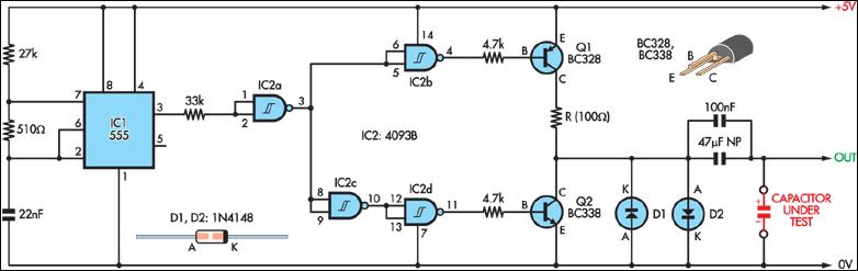 When teamed up with an oscilloscope, this simple circuit provides a means of measuring capacitor ESR.
A 555 timer (IC1) configured as a 2.3kHz free-running oscillator acts as the timebase. It provides narrow (7.7µs) pulses to the capacitor under test via a NAND Schmitt trigger (IC2) and transistor Q1.
A 100Ω resistor in series with Q1 limits current flow to about 50mA. Therefore, an ESR of 1Ω will produce pulses across the test capacitor of 50mV, which means that an oscilloscope with a vertical sensitivity of 5mV can measure ESR down to 0.1Ω or less.
Posted on Monday, January 3, 2011 • Category: Test and Measurement
 This project will explain how I build my new wattmeter.
This watt meter will be able to measure power from 300nW to 30W @ (0-500MHz).
This wattmeter is based up on a dummy load of 50 ohm which can handle 50W.
The measurement will be displayed in Watt on a 2x16 Char display.
Posted on Monday, January 3, 2011 • Category: Test and Measurement
 Electrolytic capacitors are by far the electronic parts that suffer aging soonest. If you have any electronic equipment that over the years has degraded its performance, developed quirks, sometimes ending in complete failure, the chances are good that one or more electrolytic capacitors inside it have degraded, causing the problem. Electrolytic capacitors age in several ways: They can become electrically leaky, causing a DC current through them that can make them blow up. They can shift in capacitance value. But the most common way they degrade, by far, is by unduly increasing their equivalent series resistance, which is the undesired internal resistance that appears in series with the wanted capacitance at a given frequency.
Posted on Monday, October 18, 2010 • Category: Test and Measurement
 Using a thermistor in the position shown makes a heat activated sensor. A change in temperature will alter the output of the op amp and energize the relay and light the LED. Swapping the position of the thermistor and 47k resistor makes a cold or frost alarm.
Posted on Friday, October 8, 2010 • Category: Test and Measurement
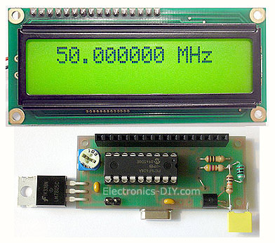 This is 60MHz Frequency Meter / Counter for measuring frequency from 10Hz to 60MHz with 10Hz resolution. It is a very useful bench test equipment for testing and finding out the frequency of various devices with unknown frequency such as oscillators, radio receivers, transmitters, function generators, crystals, etc. The meter provides very stable readings and has excellent input sensitivity thanks to onboard amplifier and TTL converter, so it can even measure weak signals from crystal oscillators. With the addition of prescaller it is possible to measure the frequency of 1GHz and above. The meter measuring range has been extended and it can now measure 60MHz instead of 50MHz.
Posted on Wednesday, October 6, 2010 • Category: Test and Measurement
 The ESR meter is perfect for any electronics repair technicians, engineers or hobbyist. This handy meter measures electrolytic capacitor equivalent series resistance (ESR) in the circuit. ESR is a very important characteristic of capacitors greater than 1 microfarad. This meter makes measurements which are often impossible to check with standard digital capacitance meters.
Posted on Tuesday, September 21, 2010 • Category: Test and Measurement
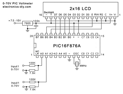
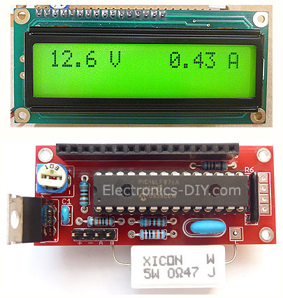 PIC Voltmeter Amperemeter can measure voltage 0-70V or 0-500V with 100mV resolution and current consumption 0-10A or more with 10mA resolution. The meter is a perfect addition to any power supply, battery chargers and other electronic projects where voltage and current must be monitored. The meter uses PIC16F876A microcontroller with built-in ADC (Analog to Digital Converter) and 16x2 green backlighted LCD display. With slight modification it is possible to measure higher voltage and current.
Posted on Friday, April 30, 2010 • Category: Test and Measurement
 This circuit is ideal for adding a low cost frequency display to a function generator or other design. I doubt if it is possible to get a cheaper design using off the shelf components!. In fact, I challenge anyone to make a cheaper design using garden variety components!.
The upper frequency limit is dependent upon the upper limit of the 74HC390 chips which is roughly 40MHz.
Posted on Tuesday, April 20, 2010 • Category: Test and Measurement
 RF Measurement has been an expensive work so far the cost of measuring RF Power Meter instruments are concerned. RF Power Meter is based on PIC16F876 microcontroller, AD8307 and 2x20 LCD display. Full documentation is included.
Posted on Monday, April 12, 2010 • Category: Test and Measurement
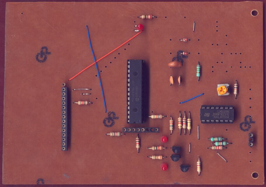
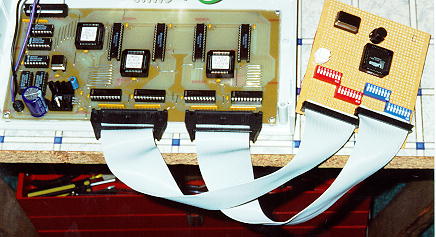 This project was published in Electronics Australia in Oct/Nov 96. It is a 32 Channel, 40Mhz, fully PC controlled TTL/CMOS logic analyzer with internal/external triggering and trigger delay. Internal triggering is fully maskable (High/Low/Don't Care) on all 32 channels. The whole things fits on one single sided PCB with virtually no wiring!
Posted on Friday, April 9, 2010 • Category: Test and Measurement
 Build your own LC Meter and start making custom made coils and inductors. This LC Meter allows to measure incredibly small inductance making it perfect tool for making all types of RF coils and inductors. LC Meter can measure inductance starting from 10nH - 1000nH, 1uH - 1000uH, 1mH - 100mH and capacitance from 0.1pF up to 900nF. The circuit includes an auto ranging and reset switch to make sure the readings are as accurate as possible.
This is a Special Edition LC Meter with upgrade to top notch components. It includes upgraded high precision capacitors, inductor, 1% Metal Film resistors and Gold Plated Machined IC Sockets, header pins and LCD header connectors. This edition is designed for professionals that require unprecedented measurement accuracy.
Posted on Friday, March 12, 2010 • Category: Test and Measurement
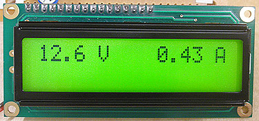 This PIC Voltmeter Amperemeter was designed to measure output voltage of 0-70V with 100mV resolution and 0-10A current with 10mA resolution. It is a perfect addition to any DIY laboratory power supply, battery chargers and other electronic projects where voltage and current consumption must be monitored. The heart of the meter is PIC16F876A microcontroller with built-in analog to digital converters and 2x16 green backlighted LCD display. Circuit design uses very few external components making it possible to fit this handy meter on a small PCB.
Posted on Saturday, August 22, 2009 • Category: Test and Measurement
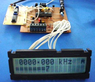
 This new 50MHz Frequency Meter is autoranging and displays the frequency in either Hz, kHz or MHz. This makes the unit easy to read, as it automatically selects the correct range for any frequency between 0.1Hz and 50MHz and inserts the decimal point in the correct place for each reading.
The design is easy to build too, since it uses a programmed PIC microcontroller to do all the clever stuff. Apart from that, there's an LCD readout, a couple of low-cost ICs, two transistors, a 3-terminal regulator and a few sundry bits and pieces to complete the design.
Note that although we have specified this Frequency Meter at 50MHz maximum, most units will be capable of measuring frequencies somewhat higher than this. In fact, our proto-type meter was capable of making frequency measurements to above 64MHz.
Posted on Saturday, August 22, 2009 • Category: Test and Measurement
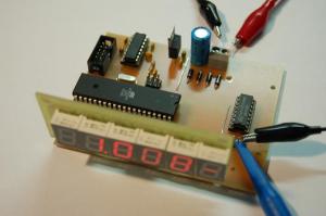
 This is a simple, inexpensive and versatile frequency counter with LCD display and some special extra features.The counter contains only three inexpensive ICs (well, add a regulator and three transistors), and operates from 6 - 15V DC at about 25mA. The most expensive single item is the LCD display, which is an industry standard 16 x 2 dot matrix module, which can often be found used or at bargain prices.
Posted on Tuesday, April 8, 2008 • Category: Test and Measurement
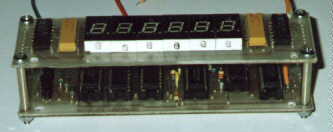
 This is 50MHz Frequency counter based on AVR.It is designed by Ulrich Radig from German.He writes:The construction of a small Frequenzzähers thanks to the current Atmel AVR controllers or even the microchip PIC controller (to name but two) relatively quickly and easily. These are mostly internal timer / counter of the controller is used. The counter is supported by the adjacent signal at high input clock counted. The timer will be the counter to a specified time ever out and reset. Let’s take a look at a 20Hz TTL signal taktet to counter it is now in the counter register for a second of value 20 This is exclusively on the display or serial interface. After a successful auction at a relevant Internet auction house, I bought some 7Segment ads, I had to think of something. The result was therefore a little cheaper said 50MHz frequency counter, which I will not be denied.
Posted on Sunday, April 6, 2008 • Category: Test and Measurement
 This is a simple to build PIC Temperature meter that allows to measure temperature in two different locations at the same time. Meter can display both Celsius and Fahrenheit values (together or individually) and is capable of measuring temperatures from -55 to 125 degrees Celsius (-67 to 257 degrees Fahrenheit). Never before such a useful and powerful circuit could be built with so little components and yet provide endless possibilities. This is all possible thanks to the use of PIC16F628 microcontroller and 2x16 character LCD display that act like a small computer which can be customizable thanks to upgradeable hex firmware.
Presented PIC temperature meter uses two very exciting DS18S20 1-Wire digital temperature sensors. Unlike regular sensors where temperature readings are passed as varying voltage, DS18S20 passes temperature information in a digital format as data. This brings many new possibilities and enables to pass temperature information over much longer distances just over a two wire cable.
Posted on Sunday, April 6, 2008 • Category: Test and Measurement
 PIC voltmeter can measure 0-70 Volts which should be more than enough for most of electronic projects providing excellent reading accuracy and resolution. It has two input channels for measuring two voltage sources at the same time. This PIC voltmeter project uses PIC16F876 microcontroller with built-in ADC (Analog to Digital Converter) and 2x16 backlighted LCD display.
Posted on Thursday, April 3, 2008 • Category: Test and Measurement
 This is one of the most accurate and simplest LC inductance / capacitance Meters that one can find, yet one that you can easily build yourself. This LC Meter allows to measure incredibly small inductances starting from 10nH to 1000nH, 1uH to 1000uH, 1mH to 100mH and capacitance from 0.1pF up to 900nF. LC Meter's circuit uses an auto ranging system so that way you do not need to spend time selecting ranges manually. Another neat function is the "Zero Out" switch that will reset the initial inductance / capacitance, making sure that the final readings of the LC Meter are as accurate as possible.
Posted on Thursday, April 3, 2008 • Category: Test and Measurement
This digital voltmeter is ideal to use for measuring the output voltage of your DC power supply. It includes a 3.5-digit LED display with a negative voltage indicator. It measures DC voltages from 0 to 199.9V with a resolution of 0.1V. The voltmeter is based on single ICL7107 chip and may be fitted on a small 3cm x 7cm printed circuit board. The circuit should be supplied with a 5V voltage supply and consumes only around 25mA.
Circuit-Zone.com © 2007-2026. All Rights Reserved.
|
|
|