Circuit-Zone.com - Electronic Projects
Posted on Tuesday, August 31, 2021 • Category: Amplifiers
This is my second encounter with LM3886. I was pleased with the sound this chip produced the first time, so I decided to make another amplifier with it. The schematic is based on the schematic in the datasheet of the chip with minor changes. I removed the time delay capacitor connected to MUTE pin, because it’s better to use separate DC protection schematic which has similar functionality. I made the output inductance L1 by winding 15 turns of enameled wire around the resistor R7. The diameter of the wire must be minimum 0.4mm. The whole was wrapped with heat shrink. I used 47uF/63V non polarized capacitor for C2. It can be regular electrolytic capacitor, but it’s better to use non-polarized or bipolar.
Posted on Monday, February 22, 2021 • Category: Amplifiers
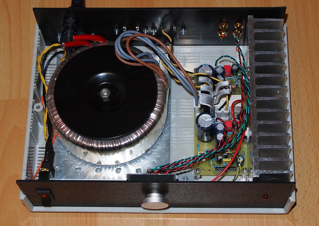
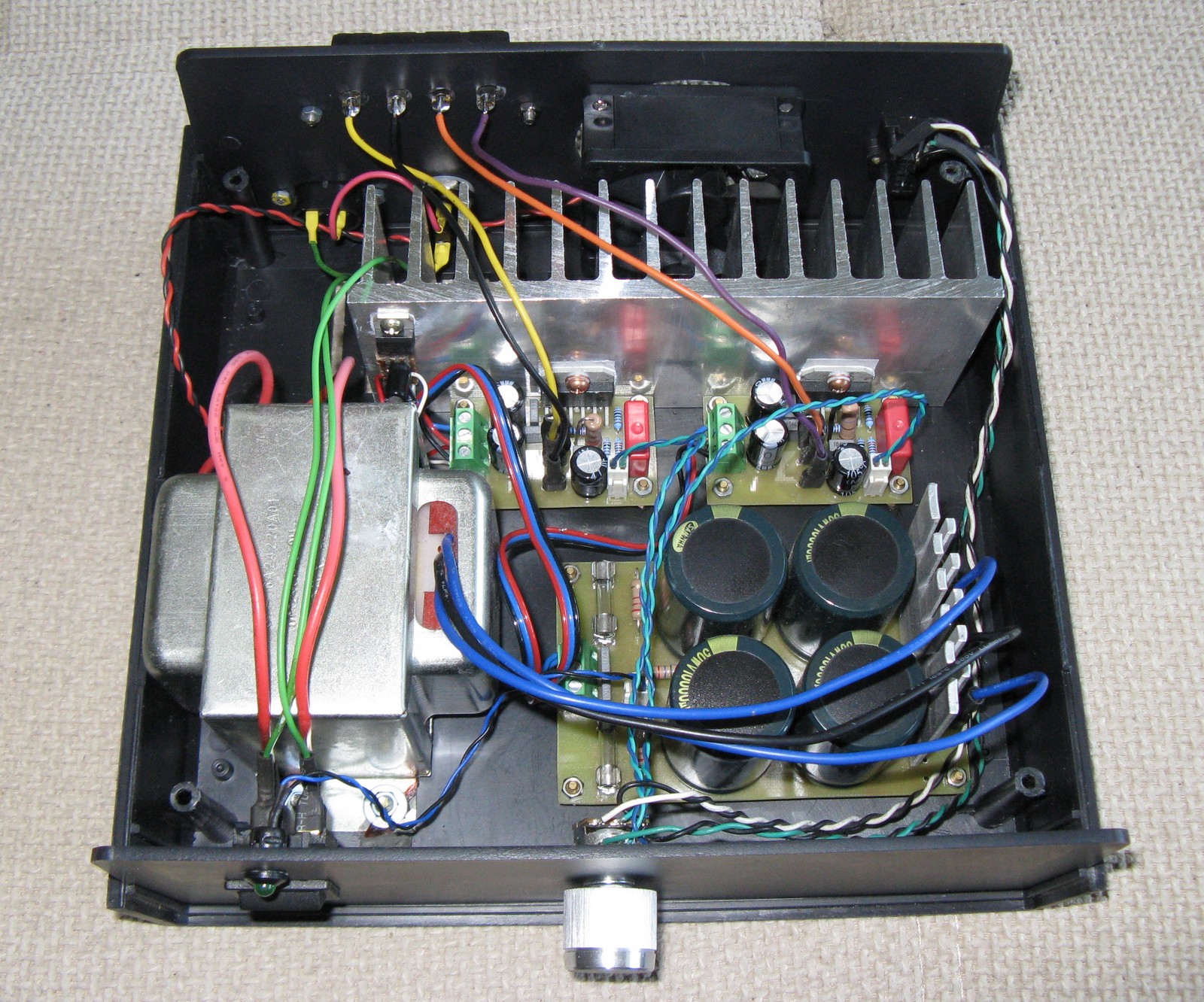
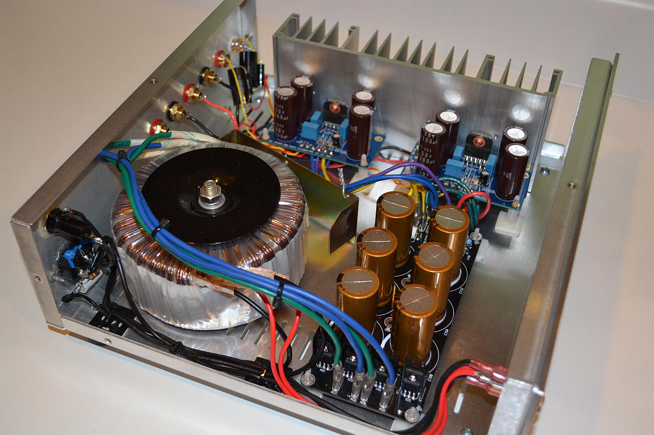
 The LM3886 is a high-performance audio power amplifier capable of delivering 68W of continuous average power to a 4? load and 38W into 8? with 0.1% THD+N from 20Hz–20kHz. The performance of the LM3886, utilizing its Self Peak Instantaneous Temperature SPiKe protection circuitry, puts it in a class above discrete and hybrid amplifiers by providing an inherently, dynamically protected Safe Operating Area. SPiKe protection means that these parts are completely safeguarded at the output against over voltage, under voltage, overloads, including shorts to the supplies, thermal runaway, and instantaneous temperature peaks. The LM3886 maintains an excellent signal-to-noise ratio of greater than 92dB. It exhibits extremely low THD+N values of 0.03% at the rated output into the rated load over the audio spectrum, and provides excellent linearity with an IMD typical rating of 0.004%.
Posted on Monday, March 23, 2020 • Category: Amplifiers
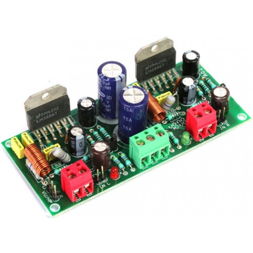
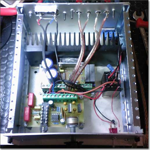
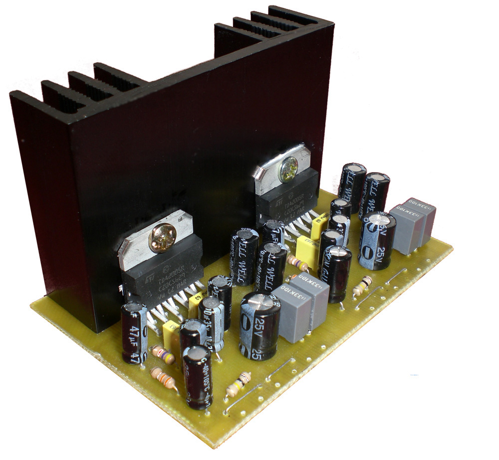
 This is 2x30W audio amplifier based on TDA2050 and LM1875. Amplifier PCB is suitable for both TDA2050 and LM1875 chips. Amplifier has all the necessary circuitry on board – power supply, speaker protection, delayed turn-on and fast turn-off. This is achieved using the convenient uPC1237 IC. TDA2050 and LM1875 are pin to pin compatible, the differences in their schematics are the values of a couple resistors and one capacitor. All this allows to make an universal circuit board, suitable for any of these two ICs.
Posted on Sunday, August 16, 2015 • Category: Amplifiers
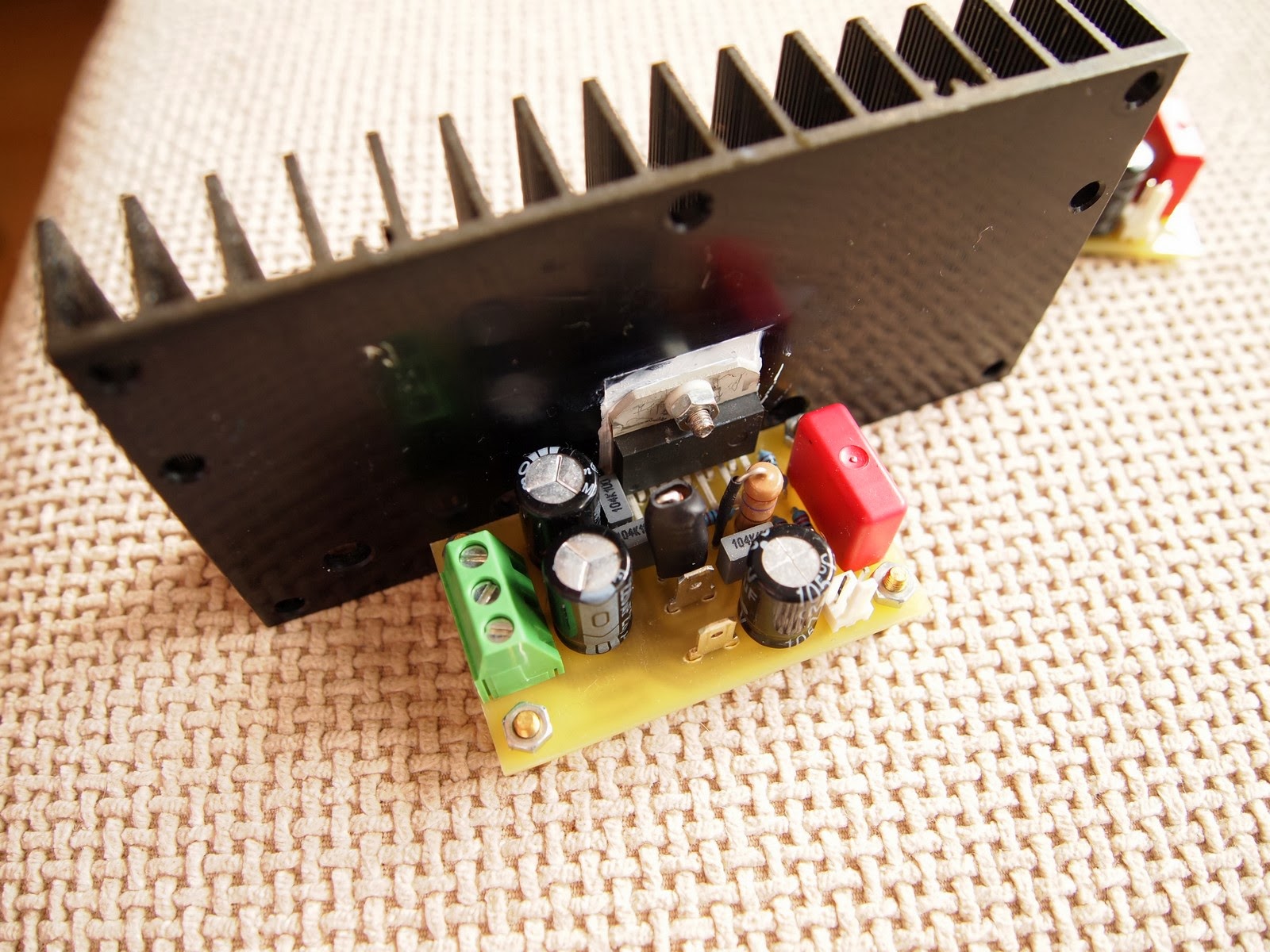
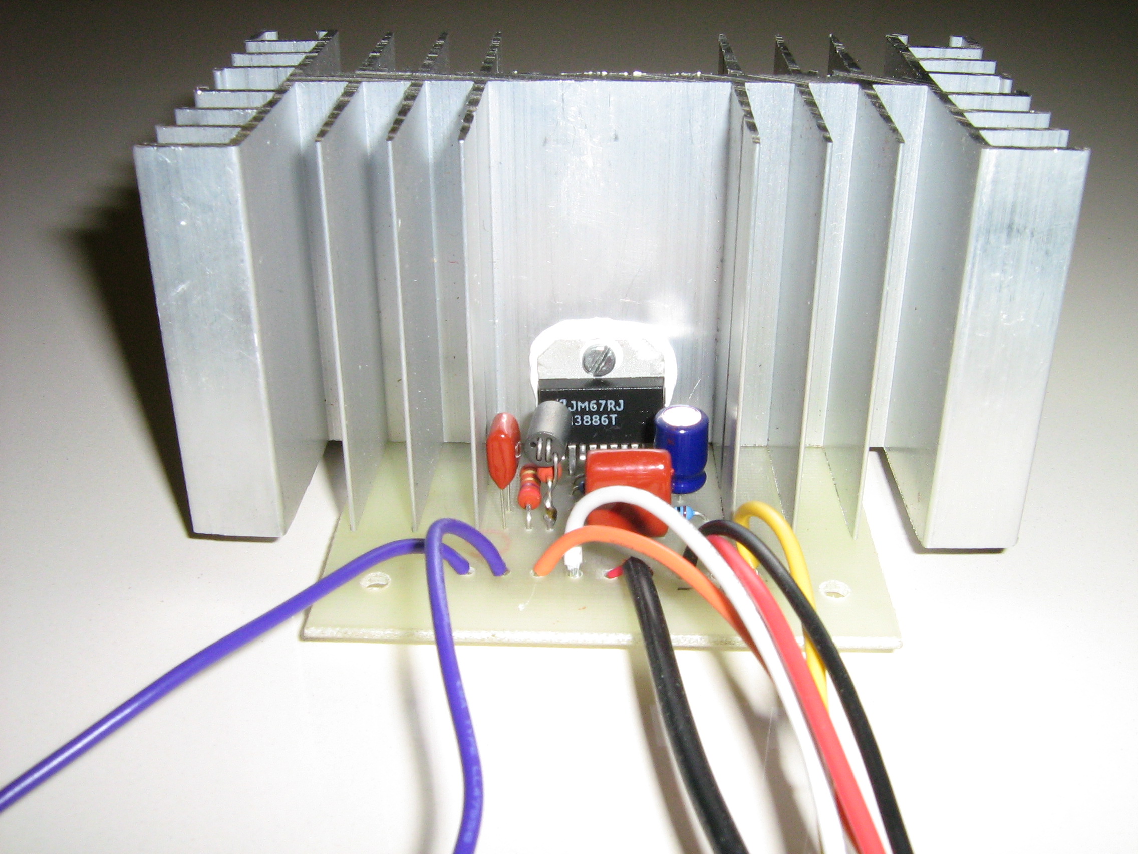
 This is a second revision of 50W LM3886 power amplifier that is used to power two bookshelf speakers. The sound produced by LM3886 chip is excellent so I decided to make another amplifier with it. The schematic is based on the schematic in the datasheet of the chip with minor changes. I removed the time delay capacitor connected to MUTE pin, because it's better to use separate DC protection schematic which has similar functionality. I made the output inductance L1 by winding 15 turns of enameled wire around the resistor R7. The diameter of the wire must be minimum 0.4mm. The whole was wrapped with heat shrink.
Posted on Friday, August 22, 2014 • Category: Amplifiers
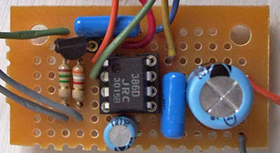 This is battery powered amplifier based on LM386 chip and has an input buffer that is feeding the inverting input. The input buffer helps to retain treble details going into the LM386 chip. It is powered from a single 9V battery.
Posted on Tuesday, July 1, 2014 • Category: Amplifiers
 It's always handy to have a little amp kicking around to trace audio signals, test mics, CD tape and TV audio outputs. You know, something that doesn't weigh a lot and isn't clumsy. There are tons of uses for this little circuit.
There are a couple of versions of this amplifier chip. Both are 8 pin DIP packages and the difference between the two are apparent by their part numbers. Either are suited for this circuit provided the supply voltage does not exceed the recommended 5 to 12 volt DC range. Power output can range from about 325 mW to about 750 mW within this supply range when using an 8 ohm speaker. Power it with batteries or a small DC supply...why not solar cells or a little windmill generator?
Posted on Thursday, February 27, 2014 • Category: Amplifiers
 LM3886 is a high-fidelity audio power amplifier IC capable of delivering 68W of continuous power using 4 Ohm speakers. LM3886 provides excellent S/N ratio of 92dB and above as well as extremely low total harmonic distortion over the audio spectrum.
LM3886 comes equipped with Self Peak Instantaneous Temperature Protection Circuitry (SPiKE) that makes it a class above other discrete and hybrid amplifiers. SPiKe Protection makes LM3886 amplifier safe against problems like over voltage, under voltage, overloads, shorts to the supplies, thermal runaway, and temperature peaks.
Posted on Sunday, June 10, 2012 • Category: Amplifiers
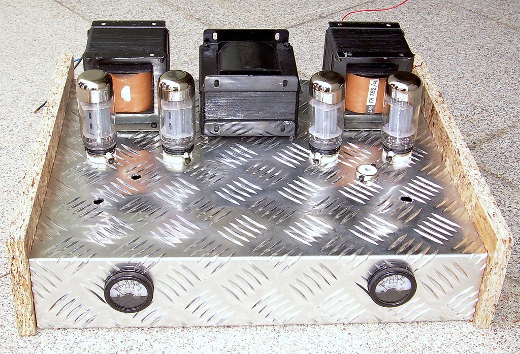
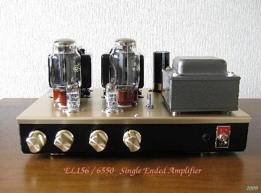 Single Ended Valve Triode Amplifier has not same tone with Push Psu Amplifier. Over 90% of Amplifiers are push pull, and push pull amplifier does not 2nd harmonic and off course
does not get 2nd 4th, 6th harmonic vs SE has 2nd, 4th, 6th harmonic. Push pull has minor distortion than SE Amplifier.2nd harmonic is make good tone for Music.not too much and not less than.feel good sound get from Single Ended Amplifiers with high efficiency speakers from 88dB/m to 100dB/m. I means Single Ended Amplifier
is almost Single Ended Triode Amplifier.or Penthode but wired Triode. Tone is Different.good for Jazz and
small room Classic.
Posted on Wednesday, May 16, 2012 • Category: Amplifiers
 Not thrilled with how a computer soundcard drove my 32ohm headphones so I decided to build myself class-A mosfet headphone amplifier. As with most of my projects, the goal was to keep it simple, keep cost down and try use some salvaged parts. This is a simple do-it-yourself (DIY) headphone amplifier project that is fashioned primarily after the Class A MOSFET Headphone Driver project by Greg Szekeres and to some extent Mark's DIY Class A 2SK1058 MOSFET Amplifier Project. The amplifier concept is simple and follows a typical single-ended class A circuit utilizing an active constant current source (CCS) in place of a passive resistor. A CCS doubles the efficiency of the circuit over that where a passive load resistor is used, bringing it to a maximum of 25%.
Posted on Tuesday, May 8, 2012 • Category: Amplifiers
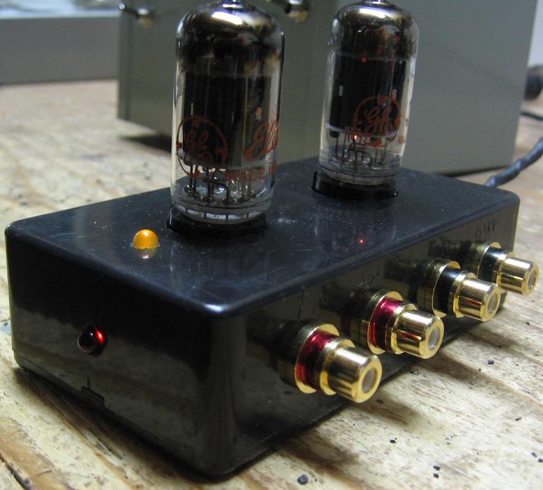 I'm not sure what motivated me to decide on building a high-gain tube preamp of this sort. Maybe it was the tube computer sound card idea I have seen, or the fact that I have enough junk to fill a dump truck. What ever it was, it all started with a cute little plastic Hammond enclosure that had been on my shelf for a couple of years. I originally thought I might use it for a tube headphone amp, but in the end realized there would not be enough space for the three tubes needed to make a head amp. This is a high gain preamplifier that is suitable for use where a lot of gain is required - to drive a power amplifier that needs plenty of gain or perhaps for use with instruments, like a guitar or microphone. If you need less gain, take a look at the RCA 12AU7 / ECC82 Cathode Follower Tube Preamp Schematic which has a gain of about 8.
Posted on Tuesday, April 10, 2012 • Category: Amplifiers
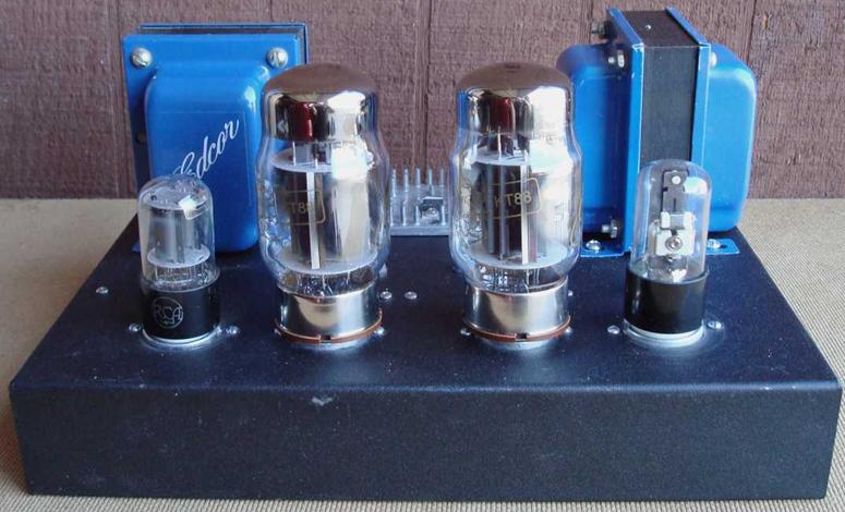 This Class-A Push-Pull Tube Power Amplifier uses a Pair of Push-Pull Class A, Ultra Linear Mono Block Tube Amplifiers that can be used with several different vacuum tubes including KT77 / 6L6GC / KT88 with a 12SL7 driver and 6NO30 tubes. The amplifier stage is based on the Compact Hi-Fi Power Amplifier. One thing about DIY audio is that it is a journey, not a destination, it never ends. One project leads to another. The only limits are time and money. DIY audio is a lot about perfection. While I was quite happy with my previous tube amplifier projects, I felt there was room to improve (here comes the journey again). I like to be involved in the music. If anything sticks out, it will degrade the experience. So I tend to like smooth response, lots of detail, wide soundstage and full spectrum of sound. These amps deliver all that in quantity. Regardless of what tubes I used for outputs, the sound is "silky" and refined.
Posted on Saturday, March 31, 2012 • Category: Amplifiers
 A general purpose audio power amplifier is a must have for the electronics amateur. It's not a good thing to use your HiFi set for an experiment, when there's a risk of blowing it's transistor out. Amplifier for your experiments should be simple in construction, durable, and easy to repair. Also a portable, low power consumption and battery powered.
Taking the considerations above, I gave you the PCB design for the TBA820M based amplifier. It is rated for 2Watts of RMS power output (16W PMPO) but gives even two times more if you cool it well by some tricks. I've been using this circuit for over ten years and personally still surprised by it's durability, thinking of how many short circuits and overdrives it is subjected.
Posted on Monday, November 28, 2011 • Category: Amplifiers
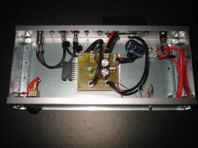
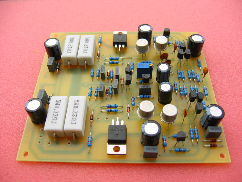
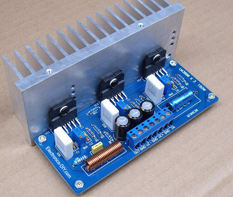 LM3886 power amplifier with 150W audio output power. Three LM3886 amplifiers are bridged together to achieve 150W. Power supply is +/- 30V. LM3886 amplifier maintains an excellent signal-to-noise ratio of greater than 92dB with a typical low noise floor of 2.0µV. It exhibits extremely low THD+N values of 0.03% at the rated output into the rated load over the audio spectrum, and provides excellent linearity with an IMD (SMPTE) typical rating of 0.004%
Posted on Friday, November 4, 2011 • Category: Amplifiers
 Here's low power stereo amplifier built around TDA2822 chip. Many people may have heard of the TDA2822 before, but for those who haven't, it is a small power amplifier that will drive two channels. It is usually in an 8-pin DIL package, but older versions I have seen are 14-pin or similar (there are datasheets for both variants). For simplicity though, my circuits show schematics for the 8-pin DIL package. The datasheet is here, provided by ST. This article is based along the usage of the TDA2822M variant of the chip series as it is commonly available. The TDA2822 is similar, but has slightly more pins so is less used.
Posted on Thursday, October 27, 2011 • Category: Amplifiers
 I built my first power amplifier when I was still in secondary school. The circuit was made of transistors, didn't provide much power and had an ugly PCB.
Around the same time I got access to a datasheet of TDA1524, a tone/volume control circuit, and I decided to use it to build a pre-amplifier, to improve the quality of the sound coming out of the amplifer. Both circuits worked well for almost a decade but the old amplifier was never up to my expectations.
In 2006 I decided that it was time to build a real power amplifier, this time based on an integrated circuit to reduce the number of external components and cost.
Posted on Monday, August 22, 2011 • Category: Amplifiers
 Several years ago, National Semiconductor came up with some very high performance, easy to use audio power amplifier LM3886 circuits. I needed an extra amp so I can bi-amp some of my homemade electrostatic speakers so I tried the LM3886 chip. LM3886 amplifier was chosen because of ease of use, performance, low distortion and a built-in protection against short circuits and thermal instability. There is not much to remove a power amp, than asking. When driving electrostatic speakers, you can not be much protection.
There are people who have “golden ears” and the feeling, provided that no application note scheme is never good enough for it to “Optimize” to “improvements” to make a claim. The problem is that most of them do not engineers and have no idea what the possible consequences of their “improvements” can be. For example, for a few years if these chips were popular with the audiophile crowd, it was all the rage at minimum power filter caps for “Best Sound” to use. We are talking about 500 uF on each power rail for each chip used LM3886 amplifier. This is clearly insufficient and leads to a distortion in the volume low enough that the power supply sags under load. The problem was that some of the golden ears of the large power supply rejection IC spec saw and thought it meant that the chip could tolerate the 10V power supply ripple. The pendulum has swung the other way, and now many music lovers are sufficient amounts of energy storage in the diet.
Posted on Wednesday, June 29, 2011 • Category: Amplifiers
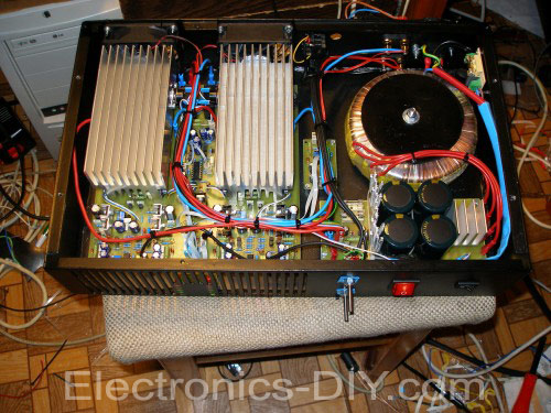
 This article describes how to build 200W Leach Amplifier from Mr. Marshall Leach known like “The Leach Amp”. Article about building of this amplifier I found later in journal A_Radio Praktická elektronika 11/2002. For many years I looked for construction of HiFi amplifier wit a good parameters, enough power reserve and simple construction. I built a couple of amplifiers with integrated circuits MBA810, TDA2005, LM3886, but I was disappointed by their output quality and noise. I decide to built a classic construction with discrete components and bipolar transistors. Construction from Mr. Dudek was interesting, but I didn’t like used components and complexity. All of my requirements satisfied construction of the Leach Amp. Circuit author publicates in a February 1976 in american journal. From these days circuit was not practically changed. Little changes are described on authors page.
I succeeded to find almost all original components on our local market, which was a miracle. Only a bigger problem was a power transformer and filter capacitors. Recommended toroid transformer for power 200W to 4 ohms is 230V/2x 42V.
Posted on Friday, June 24, 2011 • Category: Amplifiers
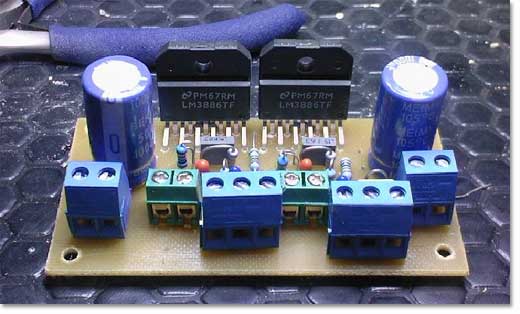
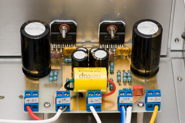 This is 100W LM3886 power amplifier. Since my DIY speaker is 4-ohm and somewhat difficult to drive, I want to have a more powerful amplifier to match with it. Therefore I designed this amplifier which uses two LM3886 per channel, in parallel circuit. This amp can deliver about 50W into a 8-ohm speaker and 100W into a 4-ohm speaker. This is a stereo amplifier and therefore 4 LM3886s are used. The LM3886 circuit is in a non-inverted configuration, so the input impedance is determined by the input resistor R1, i.e. 47k. The 680 ohm and 470pF resistor capacitor filter network is used to filter out the high frequency noise at the RCA input. The 220pF C4 and C8 capacitors are used to shot out the high frequency noise at the LM3886 input pins.
I used high quality audio grade capacitors at several locations: 1uF Auricap at the input for DC blocking, 100uF Blackgate for C2 and C6, and 1000uF Blackgate at the supply filter.
Posted on Tuesday, June 7, 2011 • Category: Amplifiers
 Complete car amplifier for subwoofer based on TDA7294 amplifier chip. This is a much powerful than previous TDA1562 based version (LINK), but its based on push-pull converter so its more difficult to build. Build-in low-pass filter, all on one one-sided 75mm x 125mm dimension PCB.
Posted on Wednesday, June 1, 2011 • Category: Amplifiers
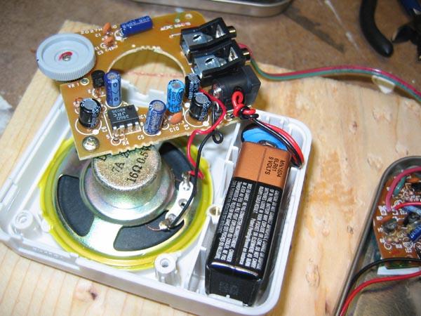
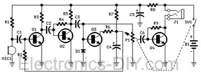 This circuit, connected to 32 Ohm impedance mini-earphones, can detect very remote sounds. Useful for theatre, cinema and lecture goers: every word will be clearly heard. You can also listen to your television set at a very low volume, avoiding to bother relatives and neighbors. Even if you have a faultless hearing, you may discover unexpected sounds using this device: a remote bird twittering will seem very close to you.
Ear amplifier is powered by 1.5V battery and draws only 7.5mA of current.
The heart of the circuit is a constant-volume control amplifier. All the signals picked-up by the microphone are amplified at a constant level of about 1 Volt peak to peak. In this manner very low amplitude audio signals are highly amplified and high amplitude ones are limited. This operation is accomplished by Q3, modifying the bias of Q1 (hence its AC gain) by means of R2.
Posted on Wednesday, June 1, 2011 • Category: Amplifiers
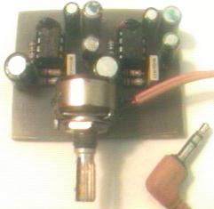
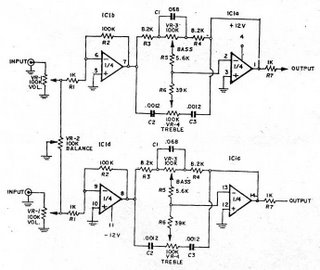
 This simple tone control (bass & treble control) can be used in may audio applications. It can be added to amplifiers, used as a stand alone control module, or even built into new and exciting instruments. It uses NE5532 IC but other ICs such as LF353 or 4558 could be used as well. It requires dual +12V,-12V power supply.
Posted on Sunday, May 29, 2011 • Category: Amplifiers
 Several years ago, National Semiconductor came out with some very high performance, easy to use audio power LM3886 amplifier ICs. I was in need of an extra amplifier so I could biamp some of my home-built electrostatic loudspeakers so I tried the LM3886 chip.
LM3886 amplifier was chosen because of the ease of use, power output, turn-on and off thump suppression, low distortion, and built-in protection against shorts and thermal runaway. There isn't much more to ask of a power amp than that. When driving electrostatic speakers, you can't have too much protection.
Posted on Saturday, May 28, 2011 • Category: Amplifiers
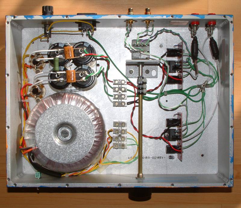
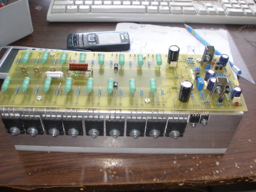
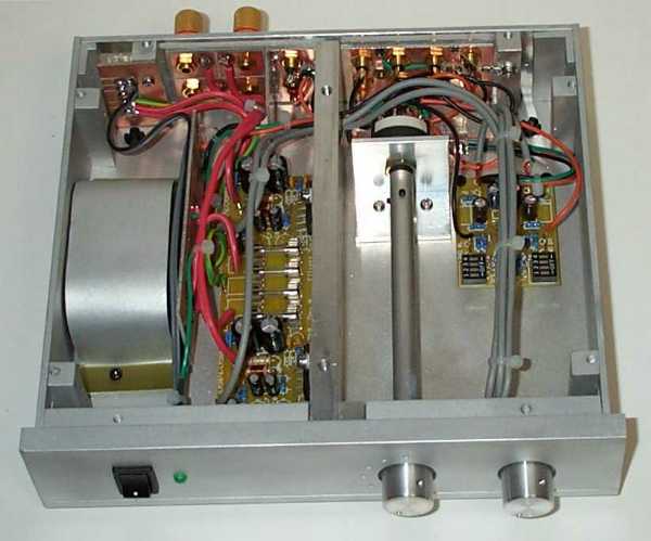
 The circuit provides both audio volume and input channel selection. A stepwise volume control is implemented with a set of small relays and resistors. In a high-end audio system, a noticable sound improvement over potentiomeneters can be obtained, also over 'audio grade' potentiometers. Clearly, the IR remote control provides convenience over solutions with stepped attenuator rotary switches. The sealed relays will maintain contact quality over a practically endless lifetime.
Posted on Thursday, May 26, 2011 • Category: Amplifiers
 LM4780 gainclone amplifier with a design similar to the National Semiconductor BPA-200 (Bridge/Parallel Amplifier) which uses 4x LM3886 per channel and an input buffer.
The total effect is (2x LM3886's paralleled amplifiers) 2x Bridged and should give approx 225 watts into 8 ohm and 335 watts into 4 ohm speakers when used with a sufficient power supply.
Posted on Thursday, May 26, 2011 • Category: Amplifiers
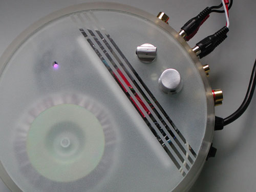
 Gainclone amplifiers have very few components and this one is based on the National Semiconductor LM3875 IC. The PCBs and components are very simple and quick to make, only took about 20 mins to assemble both amps and rectifier board. DC offset was about 80mV on one channel and about 40mV on the other. I used the optional Ci capacitor in the national datasheet for the IC which reduced it to between 0-4mV:
This is the capacitor I chose, its an Elna Starget (expensive). The case was MUCH more time consuming and difficult to make though. I bought all the aluminium from a scrap metal yard including the heatsink. I got my aluminium panels cut at a sheet metal shop as I cant make straight cuts with a hack saw.
Posted on Saturday, May 21, 2011 • Category: Amplifiers
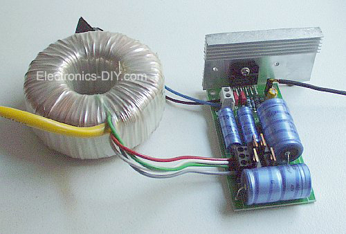
 Presented is 68 watts LM3886 Power Amplifier with the use of popular LM3886 amplifier integrated circuit. Amplifier should be fed by source symmetrical good filtered of + 34 and – 34 volts. R2 and L1 is a resistor of 10 ohms / 2watt coiled with 10 to 12 you exhale of enameled thread AWG 20. The circuit integrated lm3886 is a component easy of being found at the electronics stores, for that he is used in several projects of potency audio, some exist circuits with linked lm3886 in bridges for power of up to 150 watts. For most information on the assembly of that circuit, I suggest that sees the datasheet of the lm3886 in the site of the national semiconductors. With the information of the leaf of data you can adapt the circuit with lm3886 your needs.
Posted on Thursday, May 19, 2011 • Category: Amplifiers
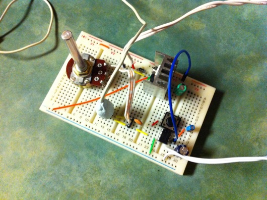
 This project shows how to build an Audio amplifier based on LM386 IC. The circuit is very simple and construction is easy on a breadboard.
The LM386 IC is unique in that the gain can be modified by changing Resistor R2 and Capacitor C2. This configuration will give us a gain of 20. By removing R2 and connecting C2 across pins 1 and 8, we can increase the gain to 200. It is important to understand that increasing the gain does not increase the output power. The increased gain is only used when a very low input signal is to be amplified.
In a previous article I discussed building audio amplifiers using discrete transistors. While it is possible to build good audio amplifiers from discrete transistors, they are no match for the many audio amp IC's available to us. IC's offer many advantages including high efficiency, high gain, low standby current, low component count, small size and ,of course, low cost. It is little wonder that audio amp IC's have replaced discrete transistors in most consumer electronic devices. While many experimenters have stayed away from these little black mysteries, I am going to uncover some of their secrets and demonstrate how easy they are to use.
Posted on Thursday, May 19, 2011 • Category: Amplifiers
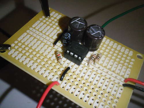
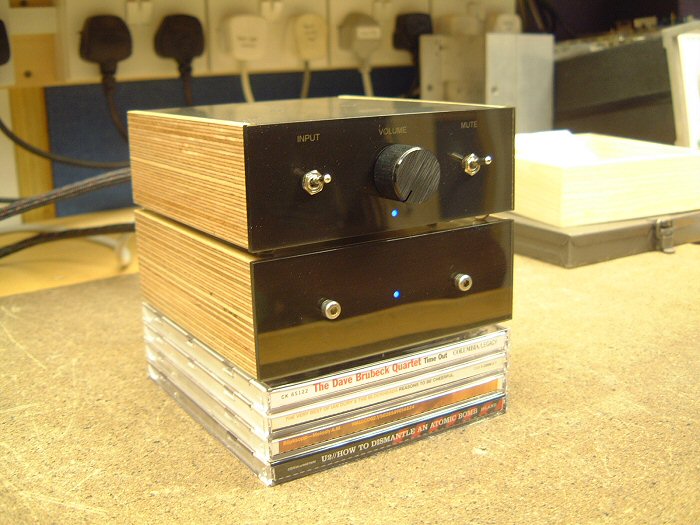 Having decided to build an ultra-compact design, using a spare LM4780 seemed like an obvious plan. Having said that, I might choose a different IC if I didn't already have one to hand. The LM4780 contains two LM3886 dies (reference) giving 60 watts per channel, which is rather more than required this application. National Semiconductor make an enormous range of IC's with differing power levels and configurations, and there are plenty of possible candidates for this application - after all, we only need a few watts as this amplifier will principally be driving small speakers on the computer desk.
Posted on Monday, May 16, 2011 • Category: Amplifiers
 This is 8W Class A Amplifier I recently built. I am very pleased with the sonic results of this amplifier. It really does not disappoint. Even using fairly standard 3 way speakers in a large room, surprisingly there is ample power. What strikes me the most is the ability of this amplifier to differentiate between instruments and noises in the sound stage. This clarity is what I like most and I think this is achieved by deceptively simple and pure circuit topology.
I used the original board layout, transistors and JFETs, and made some modifications. Heat sinking was increased to approximately triple the amount recommended. Instead of using the standard bridge rectifier, capacitor bank and battery setup, I opted for a fully regulated supply with a total of 127,0000 uF capacitance per channel and a 500 VA toroid transformer.
Posted on Wednesday, May 11, 2011 • Category: Amplifiers
 I wanted to make this HI-FI Valve Amplifier so that MCS can be considered a classic brand like a lot, but my hand veteran tuner anfimden kopamıyordum transistor amplifier at the end of this one day I decided to take it in my hand as long as I have somehow amplifier kurtulamayacaktım air after breakfast and drinking my tea I gave trying to check if the decision is correct Cry with her almost 15 years we have not shared this with less than animism, but cherish her love of rock music by pressing the send us compelled to take this tube amplifier device bitirebilecektim yes, I was sure before I took a friend who wants to
3 months without music ... without it stood late Tagged with kamçılandım ITSELF HERE:)
Posted on Friday, May 6, 2011 • Category: Amplifiers
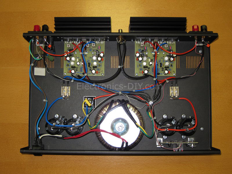
 Here's a 2x60W LM4780 Power Amplifier. LM3886 is very interested in our project was the first project, and were acclaimed. But the feedback we receive from you, from scratch, we knew we should make a complete device. One reason for that, but hard to find and the LM3886 integrated into the original cost of a fact to be taken into consideration. In this project, in which hosts two LM3886 LM4780 integrated with Integration, ie, making a complete amplifier. Advantageous LM4780 is an integrated, cost of both purchase price aşacağından sahtesinin made of forged-not-at least we do not see, but also would have received only two LM3886 price, or even more cheaply. We mean the complete amplifier, pre-amplifier, power amplifier and power supply hosts, ready for use, kutulayıp living room you can put the head in a corner of the device. If your hand if you have preamps or power amplifier, may be helpful in other projects.
Posted on Wednesday, April 20, 2011 • Category: Amplifiers
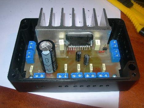 So this time I decided to make pretty simple but powerful enough car audio amplifier. For this I’ve chosen quad bridge car audio amplifier TDA7384 which has four input and four output channels with power capability of 4x35W. As datasheets of TDA7384 says it is low distortion, low output noise, low external component count. Also has Stand-By function and Mute function. It has several protections like from output short circuit to GND or to Vs, capable to handle very inductive loads, thermal limiter, load dump voltage. TDA7384 is an AB power amplifier cased in flexiwatt25 (eagle library is included in project archive) package witch is designed for high end car radio applications. It allows rail to rail output voltage swing with no need of boot-strap capacitors.
Posted on Monday, April 18, 2011 • Category: Amplifiers
 I am a big fan of surround sound. Up until the moment I finished this amp, I was using two two-channel amplifiers to power four speakers. This was very annoying, because it meant I had two volume controls. This invariably meant that the balance between front and rear was off. Added to this, was that the amplifier for the rear speakers was not very good. It produced too much noise, and allowed clicks and pops from the power grid through, to be amplified and heard. I decided I was going to build a four channel power amplifier, and later a pre-amplifier to feed it. You might wonder why I didn't choose to make a five channel one instead. This is because I don't see the use of the center channel. I will probably write an article detailing why, but for now, suffice it to say that four channels is enough for 2 dimensional sound, which is what 5.1 is as well.
Posted on Sunday, April 3, 2011 • Category: Amplifiers
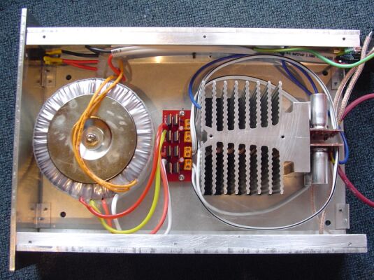
 The amp described on this page, is a very simple poweramp based on the National Semiconductor chip LM3875. According to National it's a chip meant for TVs, compact stereos etc. But many people claim that these chips are great high-end amps...
So I decided to try building one. The "design" work was quickly done, as I just used the guidelines and sample circuit of the datasheet. I designed a small PCB for the amp (I'm lazy), and I made it double sided to make it easier to keep all the ground lines separate, as recommended by National.
The prototype board can be seen below with a 100VA toroid I used for testing.
Posted on Wednesday, March 30, 2011 • Category: Amplifiers
 This 200W MOSFET Power amplifier is suitable for many applications such as Guitar Ampplifier, Mic or Home theater.
As many people prefer because of its legendary robustness of MOSFET transistors. MOSFET amplifier is rated at 200W power with 4Ω speakers. It has good frequency range of 1 dB 20Hz up to 80kHz. THD is less than 0.1% at full power and signal to noise ratio when compared to 200W is better than -100 dB unweighted.
Posted on Sunday, March 27, 2011 • Category: Amplifiers
 In this application, we are building a gaincard like amplifier. This application type is named gainclone in the audio world. To take a satisfactory audio response, we are adding equalizer to the feedback line and adding bass compensation also.
We are using LM3886 which is the revised version of its brother LM3875. These are the parameters that we are interested in. Honestly this values are much more better than many of HI-FI amplifiers sold in the market. Especially it is hard to find 110dB signal to noise ratio. And another property is, when there is no input, this amplifier is quite like a dead. It is nearly impossible to hear any noise when you stick your ear to the speakers.
Posted on Wednesday, March 16, 2011 • Category: Amplifiers
 This amplifier is based on the PA100 parallel amplifier detailed in National Semiconductor's application note - AN1192.
Since my DIY speaker is 4-ohm and somewhat difficult to drive, I want to have a more powerful amplifier to match with it. Therefore I designed this amplifier which uses two LM3886 per channel, in parallel circuit. This amp can deliver about 50W into a 8-ohm speaker and 100W into a 4-ohm speaker. This is a stereo amplifier and therefore 4 LM3886s are used. The LM3886 circuit is in a non-inverted configuration, so the input impedance is determined by the input resistor R1, i.e. 47k. The 680 ohm and 470pF resistor capacitor filter network is used to filter out the high frequency noise at the RCA input. The 220pF C4 and C8 capacitors are used to shot out the high frequency noise at the LM3886 input pins.
I used high quality audio grade capacitors at several locations: 1uF Auricap at the input for DC blocking, 100uF Blackgate for C2 and C6, and 1000uF Blackgate at the supply filter.
Posted on Wednesday, March 16, 2011 • Category: Amplifiers
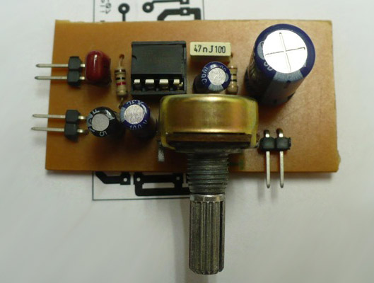 This amplifier is very easy to make and very compact, works with a single power source whose value can be between 4V and 12V.It is based on the use of a type LM386 amplifier, capable alone to issue a power of several hundreds of milliwatts to a load (HP) of 8 ohms, while consuming only a few mA at rest. Ideal for make a small portable battery powered amp. The LM386 is a power amplifier designed for use in low voltage consumer applications. The gain is internally set to 20 to keep external part count low, but the addition of an external resistor and capacitor between pins 1 and 8 will increase the gain to any value from 20 to 200.The inputs are ground referenced while the output automatically biases to one-half the supply voltage. The quiescent power drain is only 24 milliwatts when operating from a 6 volt supply, making the LM386 ideal for battery operation.
Posted on Friday, March 11, 2011 • Category: Amplifiers
 20W TDA2005 stereo amplifier for all suitable applications like amplifying medium power speakers. It is suitable for car use but before, the power supply must be choked with at least 150mH and it must give up to approximately 6 to 7 amps during the upstream performance.
Posted on Monday, March 7, 2011 • Category: Amplifiers
 Article about building Marshall 200W Leach Amplifier. For many years I looked for construction of HiFi amplifier wit a good parameters, enough power reserve and simple construction. I built a couple of amplifiers with integrated circuits MBA810, TDA2005, LM3886, but I was disappointed by their output quality and noise. I decide to built a classic construction with discrete components and bipolar transistors. Construction from Mr. Dudek was interesting, but I didn't like used components and complexity. All of my requirements satisfied construction of the Leach Amp. Circuit author publicates in a February 1976 in american journal. From these days circuit was not practically changed. Little changes are descripted on authors page.
Posted on Friday, February 25, 2011 • Category: Amplifiers
 Here's a Leach Amplifier based on 2SC5200 and 2SA1943 output power transistors that can provide up to 700W of power. The mechanical design is relatively simple, the transistors are placed on the two cooling profiles with a height of 66 mm, width 44mm, overall length 260mm. They are turned against each other Thus, from the cooling tunnel. Coolers are attaching the nylon backing which allows the assembly of transistors without washers, and thus better transfer of heat. DPS amplifier is at the top of the tunnel and the transistors are soldered from the bottom of PCB.
Posted on Friday, February 18, 2011 • Category: Amplifiers
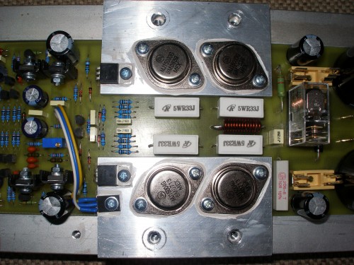 The amplifier design includes not only the final stage of the source (rectifier, filter) and protection against DC voltage output amplifier and speaker connections delayed.
As already mentioned, the amplifier is designed as a single-module. This means that on one common board rectifier, filter capacitors, protection And definitely amplifier.
Regarding the components of the external solution, the solution based on the original Mr. Marshall Leach. The proposal is adapted for the proposal. in the amplifier are used for temperature sensing diodes are replaced with one sensing transistor mounted on the end of the main condenser and field Tranda. This transistor provides a thermal feedback and thus of a stable quiescent current amplifiers.
Privacy speakers are powered directly from the voltage amplifier. As for mechanical design, is probably the most complicated in the whole amplifier. Cooling is done by the Al blocks that are attached to the main cooling profile. ZH6465 profile is used. The terminal transistors to heat is released through Al strips with a thickness of 6 mm in the lateral beams and passing into the cooler. more pictures.
Posted on Tuesday, February 15, 2011 • Category: Amplifiers
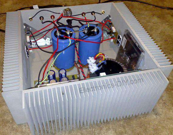
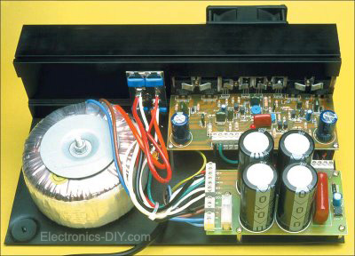
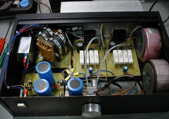
 After I built several LM3875 and LM3886 gainclone amplifiers, I was totally impressed by their audiophile sound quality. My design goal is to create a audio power amplifier that can deliver 300W into my 4-ohm DIY speaker with low distortion. I want it to produce deep, tight and punchy bass while keeping the excellent mids and highs from my other gainclones. My design uses a PCB to hold 3 paralleled 3886s (i.e. PA150), and then I use the DRV134 to bridge 2 of the PA150 PCB boards. The function of DRV134 is to convert the un-balanced input signal to a balanced signal, so that the non-inverted signal is fed to one PA150, and the inverted signal is fed the another PA150. One of the PA150 is connected to the speaker's positive input, and the other PA150 is connected to the speaker's negative input. Because of this push-pull configuration, the total gain of the amplifier is doubled. Each PA150 has a gain of 20, so the gain of the BPA300 is 40.
Posted on Thursday, February 10, 2011 • Category: Amplifiers
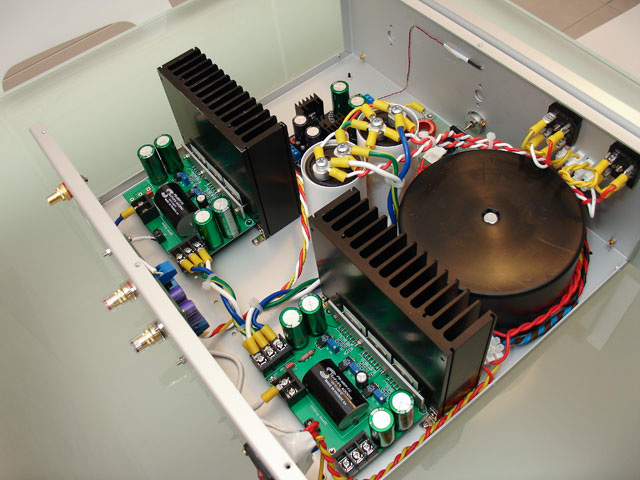
 400W Stereo Audio Amplifier based on the original Marshall Leach involvement, but has made some improvements. Regarding the power supply voltage to the +-75V. VC comparing the performance of the modified Leach 700W/2R on one common board of both channels, as well as protection and control circuits for the fans. Compared to the 700W version a bit different in wiring. Because some things in the 700W version is completely tightened to perfection.
Posted on Sunday, January 30, 2011 • Category: Amplifiers
 It is a 2x56W stereo amp based on National Semiconductor's LM3876T chip (they come in 2 versions T and TF the latter having an insulated case), this type of amp is also known as a gainclone because it is an improved copy of Gaincard amplifier. seriously this amp can outperform most commercial amplifiers/receivers (minus the video upscaling/switching) when built properly ie it has very low THD you will not be disappointed by how good it sounds . When connected to AV equipment such as dvd players this thing gets insanely loud (despite having only 56W per channel), i've have never required more than 25% volume because it hurts my ears NOTE: a even
more powerful version using the same circuit with a LM3886 chip can be made giving 68W per channel.
Posted on Sunday, January 30, 2011 • Category: Amplifiers
 Many electronic projects require the use of a small audio amplifier. Be it a radio transceiver, a digital voice recorder, or an intercom, they all call for an audio amp that is small, cheap, and has enough power to provide adequate loudness to fill a room, without pretending to serve a disco! About one Watt RMS seems to be a convenient size, and this is also about the highest power that a simple amplifier fed from 12V can put into an 8 Ohm speaker. A very low saturation amplifier may go as high up as 2 Watt, but any higher power requires the use of a higher voltage power supply, lower speaker impedance, a bridge circuit, or a combination of those.
During my many years building electronic things I have needed small audio amps many times, and have pretty much standardized on a few IC solutions, first and and foremost the LM386, which is small, cheap, and very easy to use. But it does not produce high quality audio... For many applications, the advantages weigh more than the distortion and noise of this chip, so that I used it anyway. In other cases I used different chips, which perform better but need more complex circuits. Often these chips were no longer available the next time I needed a small amplifier.
Posted on Thursday, January 27, 2011 • Category: Amplifiers
 The following is a 70W amplifier based on a popular TDA7294 chip. Main technical characteristics of the amplifier are as follows: input resistance - 22 kOhm input voltage - 750 mV nominal output power at 4 ohms and THD 0.5% - 70 Watts Frequency Range - 20 ... 20000 Hz supply voltage - ± 27 V, quiescent current - 60 mA. The amplifier has a built-in thermal protection, and protection against overload and short circuit in the load. For "soft" switching amplifier is SA1. Switch can be powered from a bipolar unregulated power supply. Power AC Transformer - 250-A, the secondary winding should be designed to current than 5A.
Posted on Friday, January 14, 2011 • Category: Amplifiers
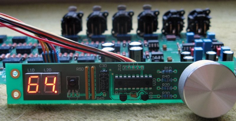
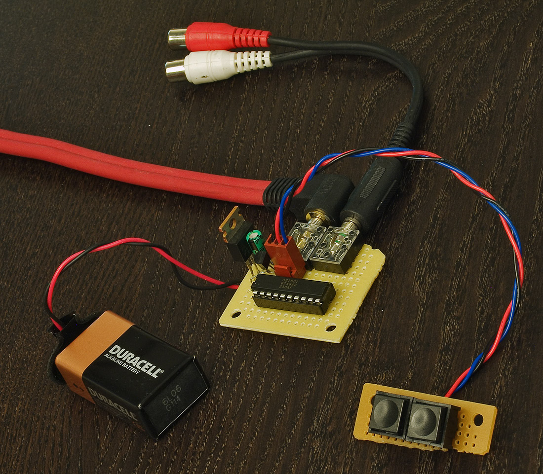 DS1802 is a Stereo Digital Volume Control IC. It consists of two 65-position, 45kΩ digital potentiometers with logarithmic resistance properties incrementing 1dB per step. It can be operated under automatic software control via a serial 3-wire interface where wiper settings are written with 8-bit words, or under push button control with simple contact closure. The part can be used in either 3V or 5V environments and anywhere within the industrial temperature range of -40°C to +85°C. The DS1802 supports daisy-chaining with other devices under single-processor control.
Posted on Wednesday, November 17, 2010 • Category: Amplifiers
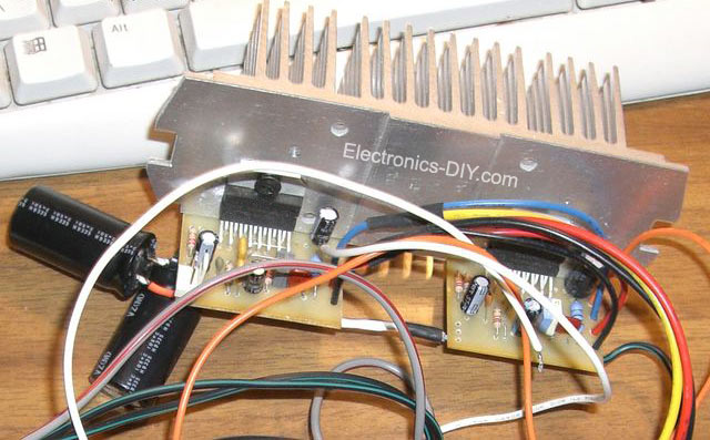
 This is a 100W Transistor based Power Amp Circuit. It's an old circuit, but nice circuit amplifier. Uses transistors MJ15003 and MJ15004, power supply +38V,-38V 3A.
Output power is 100W for 8 OHM Speaker.
Posted on Wednesday, November 17, 2010 • Category: Amplifiers
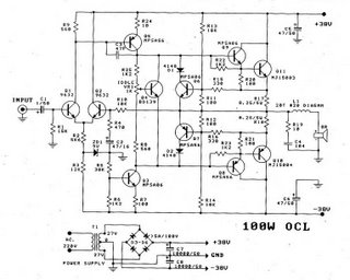
 This is old circuit Power amp OCL, But easy circuit and very nice. To use for play music in your home. It low cost too. It use IC 741 or LF351(good) and Transistor x 4 (2N3055+MJ2955+BD139+BD140) and little component. Power supply volt +35V/-35V and 3A for Mono, 5A for Stereo.
Posted on Wednesday, November 17, 2010 • Category: Amplifiers
 PCB Tone control adjustable bass-treble Stereo by IC LM348
Posted on Wednesday, November 17, 2010 • Category: Amplifiers
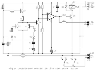 This is a small protection circuit from loudspeakers, from DC voltage that likely to exist after some damage in the power amplifier. If a DC voltage is presented in the exit of amplifier, RL1 it interrupts immediately the line of loudspeakers preventing thus to reach in he. Parallel it provides a delay time of 3 seconds from the moment where the power supply will be applied. This delay protects the loudspeakers from undesirable bangs that are observed when open the supply switch.
Posted on Wednesday, November 17, 2010 • Category: Amplifiers
 Circuit of TDA2030 amp OTL 15W
Posted on Wednesday, November 17, 2010 • Category: Amplifiers
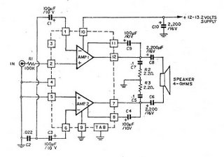 This is circuit Car audio Amplifier(Bridge Amplifier BCL) , It use IC HA1377, Supply Volt 12V-13V. Speaker 4 OHM. Nice Circuit and Easy to Build.
Posted on Tuesday, October 19, 2010 • Category: Amplifiers
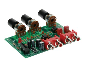
 The mixer circuit below has 3 line inputs and 3 mic inputs. The mic inputs are suitable for low impedance 200-1000R dynamic microphones. An ECM or condenser mic can also be used, but must have bias applied via a series resistor.
Posted on Monday, October 18, 2010 • Category: Amplifiers
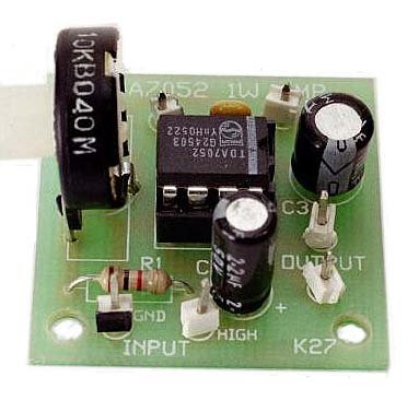 This circuit is a 1 watt mono amplifier using the TDA 7052 from Philips. It is designed to be used as a building block in other projects where a battery powered audio amplifier is required to drive a small speaker. It will operate best from 6 – 12 V DC and requires no heatsink for normal use.
Posted on Monday, October 18, 2010 • Category: Amplifiers
 The Circuit present here is a 20Watts Car Stereo Amplifier. The main features of this powerful MULTIWATT® package (a trademark of SGS-THOMSON Microelectronics), a power amplifier IC chips designed specifically for car radio application, are the high current capability (3.5A) and the capability to drive a very low impedance (down to 1.6R). Here is the schematic diagram of the standard circuit as shown in its data sheet.
Posted on Tuesday, April 27, 2010 • Category: Amplifiers
 The amp is based on the Project 19 PCB, so uses a pair of LM3876 (or LM3886) power opamps, run from a ±35V supply. I used a cut-down P88 preamp PCB because I only wanted one preamplifier stage, but the entire board can also be used. Alternatively, the P19 amp can be run at higher gain than normal, alleviating the need for a preamp at all. The down side of this is that the noise level will be higher, and background noise may be audible with efficient speakers and/ or very quiet surroundings.
Posted on Tuesday, April 13, 2010 • Category: Amplifiers
 This simple amplifier shows the LM386 in a high-gain configuration (A = 200). For a maximum gain of only 20, leave out the 10 uF connected from pin 1 to pin 8. Maximum gains between 20 and 200 may be realized by adding a selected resistor in series with the same 10 uF capacitor. The 10k potentiometer will give the amplifier a variable gain from zero up to the maximum.
Posted on Saturday, August 22, 2009 • Category: Amplifiers
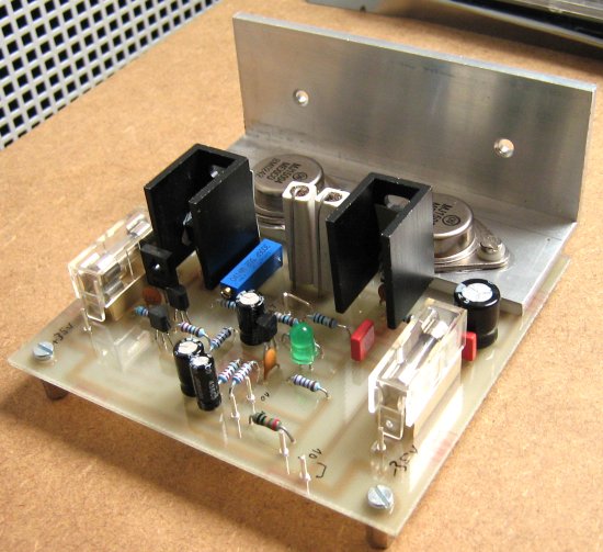
 I was in my final 6 month work term with an electronics company as a trainee. Within this company there are a few audiophiles who are tube lovers and spend astronomical amounts of money on their audio equipment. My training supervisor had found Mark's Class A MOSFET Amplifier Project and suggested that I design a PCB and build this project as part of my training.
I followed the Class A MOSFET Amplifier Schematic with the following exceptions. Instead of the 2SK1058, I used the 2SK2221 mosfet which I had on hand. I compared the datasheets of the 2SK1058 and the 2SK2221 and the differences between the two were very small. The other change was to use a 6800 uF capacitor on the output instead of a 4700 uF capacitor.
Posted on Sunday, November 9, 2008 • Category: Amplifiers
 This article descripts, how I built amplifier from Mr. Marshall Leach known like "The Leach Amp". I built amplifier from the original instructions on these pages: http://users.ece.gatech.edu/~mleach/lowtim/. Article about bulding of this amplifier I found later in journal A_Radio Praktická elektronika 11/2002. For many years I looked for construction of HiFi amplifier wit a good parameters, enough power reserve and simple construction. I built a couple of amplifiers with integrated circuits MBA810, TDA2005, LM3886, but I was disappointed by their output quality and noise. I decide to built a classic construction with discrete components and bipolar transistors. Construction from Mr. Dudek was interesting, but I didn't like used components and complexity. All of my requirements satisfied construction of the Leach Amp. Circuit author publicates in a February 1976 in american journal. From these days circuit was not practically changed. Little changes are descripted on authors page.
Posted on Monday, May 5, 2008 • Category: Amplifiers
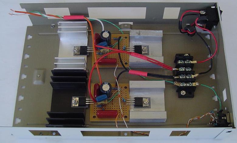
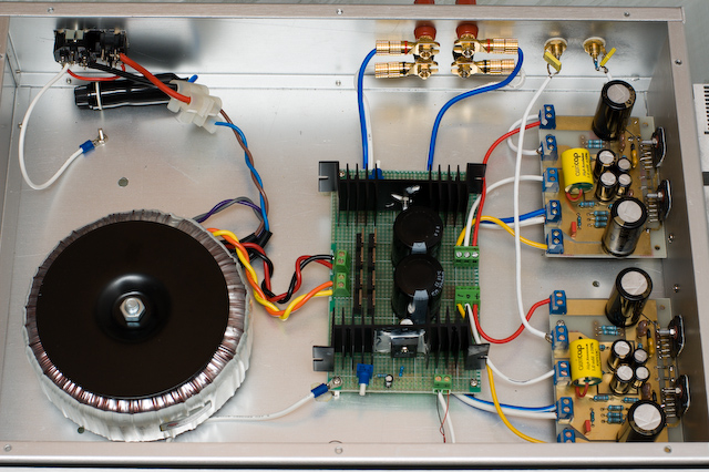
 This a LM3886 amplifier that features both balanced (XLR) and unbalanced (RCA) audio inputs.
I've changed the internal circuits of this ChipAmp or so called "GainClone" to use premade circuit boards. The reason for this is that the bass/ low frequency response of the prior version was not as powerful as I would have liked. It is said that simply adding more capacitance to the power supply improves this, but worsens the high frequency characteristics. Boards use a noninverting amplification scheme, versus the inverting circuit I had used previously, I have heard some people mention that noninverting is better in some respects so wanted to try it. At the bottom of the page you will see the different schematics for the inverting and noninverting designs. In addition, Images will now load in a new window.
Posted on Saturday, May 3, 2008 • Category: Amplifiers
 Gainclone in the inverted mode with the pot at its input is great amplifier, so it will work fine without any preamp or input buffer. However, here is a suggestion for the further improvement of some parameters of the sound of the inverted gainclone. During experiments, I paid special attention not to loose the good sides of the original, unbuffered inverted gainclone.
Posted on Wednesday, April 23, 2008 • Category: Amplifiers
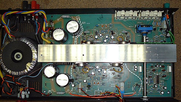 Musical Fidelity would let you believe that this is a Class A design. However, in common with most commercial amplifiers, it is a class AB amplifier - it simply has a rather high standing current in the output stage, which results in the first 8 watts or so being class A.
Posted on Friday, April 11, 2008 • Category: Amplifiers
GainClones have VERY few components and this one is based on the National Semiconductor LM3875 IC. The PCBs and components are very simple and quick to make, only took about 20 mins to assemble both amps and rectifier board. DC offset was about 80mV on one channel and about 40mV on the other. I used the optional Ci capacitor in the national datasheet for the IC which reduced it to between 0-4mV: This is the capacitor I chose, its an Elna Starget (expensive). The case was MUCH more time consuming and difficult to make though. I bought all the aluminum from a scrap metal yard including the heatsink. I got my aluminum panels cut at a sheet metal shop as I cant make straight cuts with a hack saw.
Circuit-Zone.com © 2007-2026. All Rights Reserved.
|
