Circuit-Zone.com - Electronic Projects
Posted on Thursday, May 9, 2013 • Category: Sensors
Park Assist circuit was designed as an aid in parking the car near the garage wall when backing up. LED D7 illuminates when bumper-wall distance is about 20 cm., D7+D6 illuminate at about 10 cm. and D7+D6+D5 at about 6 cm. In this manner you are alerted when approaching too close to the wall. All distances mentioned before can vary, depending on infra-red transmitting and receiving LEDs used and are mostly affected by the color of the reflecting surface. Black surfaces lower greatly the device sensitivity. Obviously, you can use this circuit in other applications like liquids level detection, proximity devices etc.
Posted on Monday, December 12, 2011 • Category: Sensors
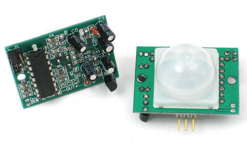 Presented schematic shows how to build simple PIR motion detector sensor. PIR sensors allow you to sense motion, almost always used to detect whether a human has moved in or out of the sensors range. They are small, inexpensive, low-power, easy to use and don't wear out. For that reason they are commonly found in appliances and gadgets used in homes or businesses. They are often referred to as PIR, "Passive Infrared", "Pyroelectric", or "IR motion" sensors.
PIRs are basically made of a pyroelectric sensor (which you can see above as the round metal can with a rectangular crystal in the center), which can detect levels of infrared radiation. Everything emits some low level radiation, and the hotter something is, the more radiation is emitted. The sensor in a motion detector is actually split in two halves. The reason for that is that we are looking to detect motion (change) not average IR levels. The two halves are wired up so that they cancel each other out. If one half sees more or less IR radiation than the other, the output will swing high or low.
Posted on Tuesday, July 12, 2011 • Category: Sensors
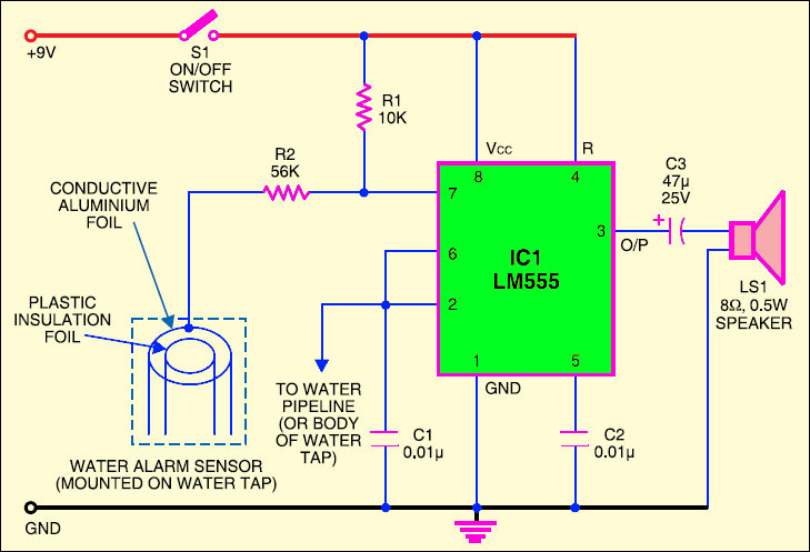 This is a simple water alarm. At the heart of this circuit is a small water sensor. For fabricating this water sensor, you need two foils—an aluminium foil and a plastic foil. You can assemble the sensor by rolling aluminium and plastic foils in the shape of a concentric cylinder. Connect one end of the insulated flexible wire on the aluminium foil and the other end to resistor R2. Now mount this sensor inside the water tap such that water can flow through it uninterrupted. To complete the circuit, connect another wire from the junction of pins 2 and 6 of IC1 to the water pipeline or the water tap itself.
Posted on Monday, July 11, 2011 • Category: Sensors
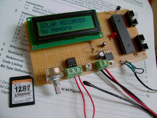 Build a simple data recorder for solar energy lab. The Recorder uses a calculator solar cell as the input sensor and a Multimedia Memory Card for nonvolatile data storage.
The device used for measuring daily insolation has been developed. The device was built with a PIC18F458 and the 128MB Multimedia Memory Card, MMC. The solar radiation is measured by a calculator solar cell. The PIC chip interfaces the MMC using SPI mode. The interval between samples is set to one minute. The firmware detects the memory card, assigns the file name and begins recording automatically. The LCD displays the file name, current sample and real-time ADC data. With the MMC flash technology and a cheap media card reader, the devices will be able to record huge amount of data and quick data uploading to the PC.
Posted on Friday, May 20, 2011 • Category: Sensors
 As shown in the schematic, temperature sensor of our electronic thermometer is LM35DZ. There are some kinds of LM35 IC, since it is cheap and easy to find we used LM35DZ in our project. It measures from 0°C to 100°C with a very linear output graph.For one degree change, it increases its output 10mV. On the Electronic Thermometer Schematic other hand, this circuit measures temperature values only between +10°C and +39°C.
2 numbered (middle) pin of the sensor is connected to the 5 numbered pins of LM3914 ICs. So every IC determines how many leds of bargraph will bright due to the analog signal received from the sensor. 2.2 microfarad tantal capacitors are connected between the 2 and 3 numbered pins of LM3914. Resistors in the circuit have %1 tolerance values.
Posted on Friday, May 13, 2011 • Category: Sensors
 A simple light / dark activated relay switch circuit, suitable for many applications like the automatic switching of the lights in a shop window or a room according to the ambient light level. The circuit uses a light dependent resistor (LDR). A light/dark option has been incorporated. The term 'light/dark' is used because the circuit has a PCB-mounted switch on board. In one switch position a light-to-dark transition will activate the relay. In the other position a dark-to-light transition is required. So you can use the falling light on the detector to switch on a normally off circuit or switch off a normally on circuit. The relay is on when LDR uncovered and relay off when LDR covered. Adjust VR1 for light sensitivity. LED will turn on at the same time with relay.
Posted on Thursday, May 5, 2011 • Category: Sensors
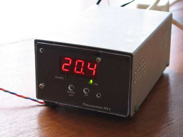 I needed to replace two old, unreliable thermostats for controlling the heating and cooling for a large garden shed.
Commercial basic digital thermostats are available quite cheaply, but some lack the ability to control heavy loads or have the extra features that I require for saving energy when the door is often left open or to indicate temperature being out of range etc.
I like the PIC18F1320 microcontroller used in my previous project - so decided to use it again in a very similar design to drive three multiplexed LED displays and read the temperature from a Dallas/Maxim DS18x20 "1-Wire" digital sensor.
Posted on Wednesday, May 4, 2011 • Category: Sensors
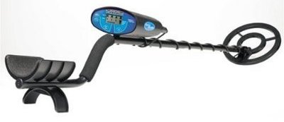 Nowadays, metal detection has become a hobby of many people. Besides as a funny and interesting hobby for them, they also wished indeed a treasure that is embedded in the soil when excavated. For this one hobby, you have to have a tool known as a metal detector.
To undergo this hobby is quite expensive to buy. But for those of you who want to try to make yourself a metal detector, the following will be presented a simple schematic that relates to metal detection.
The operation of metal detector is based on superheterodying principle, which is generally used in a heterodyne receiver. This circuit uses two RF oscillators. Both oscillator frequency is fixed at 5.5 MHz. The first RF oscillator comprises transistor T1 (BF 494) and 5.5 MHz ceramic filter commonly used in TV sound-IF section.
The second oscillator is an oscillator Colpitt realization with the help of the transistor T3 (BF494) and inductor L1 (follow the details of construction) was driven by trimmer capacitor VC1.
Posted on Thursday, April 28, 2011 • Category: Sensors
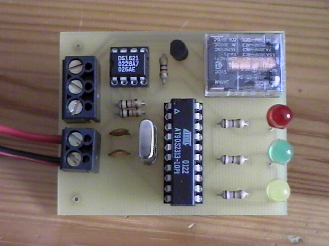 This circuit uses a Dallas DS1621 temperature sensor which indicates the temperature of the device. The temperature sensor has an thermal alarm output, which becomes high when the temperature of the device exceeds a user defined value. When the temperature drops below a user defined value, the alarm output becomes low. In this way any amount of hysteresis can be programmed. The values are stored in a special register of the device that is nonvolatile. The signal of the alarm output is amplified by a BC557 PNP transistor, that drives a relay that can switch a heater element or a blower on or off. The temperature settings and readings are communicated to/from the device over a simple 2-wire serial interface. An ATMEL 90S2313 microcontroller controls the serial communication to/from the DS1621.The microcontroller also controls three LED, only one of the LED's is on when the temperature is within a certain range. The range of the temperature in which the LED's are on can be set by the user in the program code. The circuit needs to be powered by a 5V power supply, which can be obtained from a wall-wart.
Posted on Tuesday, April 26, 2011 • Category: Sensors
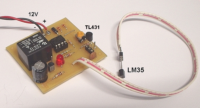 Here is a simple yet highly accurate thermal control circuit which can be used in applications where automatic temperature control is needed. The circuit switches a miniature relay ON or OFF according to the temperature detected by the single chip temperature sensor LM35DZ. When the LM35DZ detects a temperature higher than the preset level (set by VR1), the relay is actuated. When the temperature falls below the preset temperature, relay is de-energized. The circuit can be powered by any AC or DC 12V supply or battery (100mA min.)
Posted on Monday, April 25, 2011 • Category: Sensors
 This circuit will turn on/off 12V DC fan or CPU fan when temperature above normal temperature.You can set turn on temperature by adjust VR1. This circuit use an NTC (Negative temperature coefficient)which is a thermistor is one in which the zero-power resistance decreases with an increase in temperature. So If temperature increase the voltage at pin 3 on LM311 will decreased .The resistance of NTC is about 10K at 25'c.
Posted on Tuesday, April 19, 2011 • Category: Sensors
 With this simple circuit you will be able to control the speed of a DC fan according to temperature measured by a temp sensor. It’s an ideal add-on for your PC cooling fans to eliminate produced noise. Requested by some correspondents, this simple design allows an accurate speed control of 12V dc fan motors, proportional to temperature.
A n.t.c. Thermistor (R1) is used as temperature sensor, driving two directly coupled complementary transistors wired in a dc feedback circuit.
An optional circuitry was added to remotely monitor fan operation and to allow some sort of rough speed indication by means of the increasing brightness of a LED.
Posted on Friday, December 17, 2010 • Category: Sensors
 The MCP9700, MCP9700A, MCP9701 and MCP9701A Temperature Sensors from Microchip offer exceptional performance for the low price. Each have different temperature ratings and accuracy parameters. MCP9700, MCP9700A, MCP9701 and MCP9701A sensors are available in different packaging and are very simple to interface with. Vdd, GND and Vout are all that are required. You should check the datasheet to get a better idea of the parameters for the device you decide to use, though keep in mind that the user module listed below will automatically calculate the temperature depending on the device in use.
Posted on Sunday, May 2, 2010 • Category: Sensors
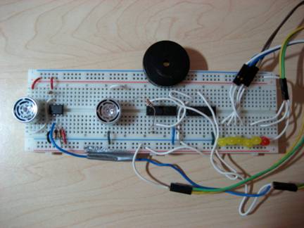 The basic theory behind the Parking Assistant is the Sound Navigation and Ranging (SONAR) technique that is used for finding the distance and direction of a remote object underwater by transmitting sound waves and detecting reflections from it. First, a series of short ultrasonic pulses are transmitted using a transducer that changes voltage into sound waves. The transmitted pulse is reflected off an object, and the reflected wave is then received by another transducer that converts sound waves into voltage. The transmitted signal is also known as the ‘ping’ and the received signal is known as the ‘pong’. By counting the elapsed time between the ping and the pong, the distance between the device and an object can be easily calculated by multiplying the elapsed time with the speed of sound.
Posted on Thursday, April 15, 2010 • Category: Sensors
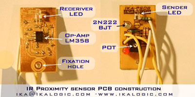
It is the same principle in ALL Infra-Red proximity sensors. The basic idea is to send infra red light through IR-LEDs, which is then reflected by any object in front of the sensor.
Then all you have to do is to pick-up the reflected IR light. For detecting the reflected IR light, we are going to use a very original technique: we are going to use another IR-LED, to detect the IR light that was emitted from another led of the exact same type!
This is an electrical property of Light Emitting Diodes (LEDs) which is the fact that a led Produce a voltage difference across its leads when it is subjected to light. As if it was a photo-cell, but with much lower output current.
Circuit-Zone.com © 2007-2026. All Rights Reserved.
|
|
|