Circuit-Zone.com - Electronic Projects
Posted on Thursday, June 11, 2026 • Category: FM Transmitters
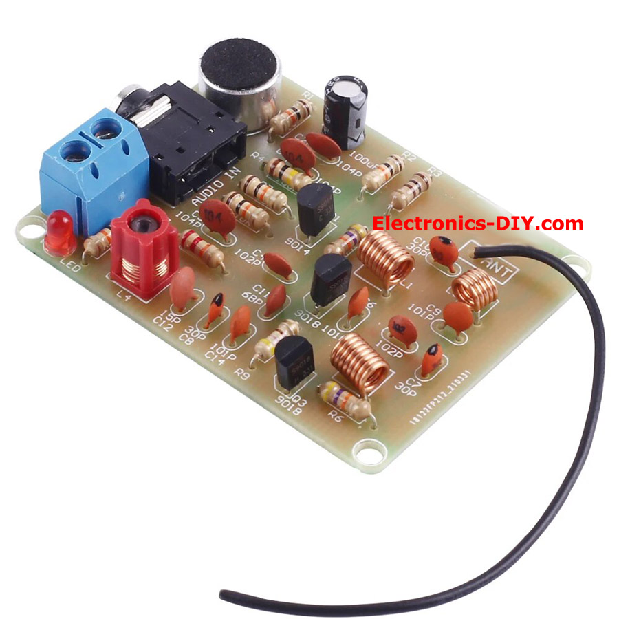
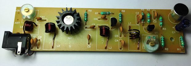
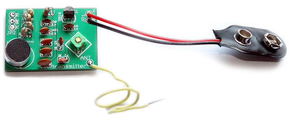
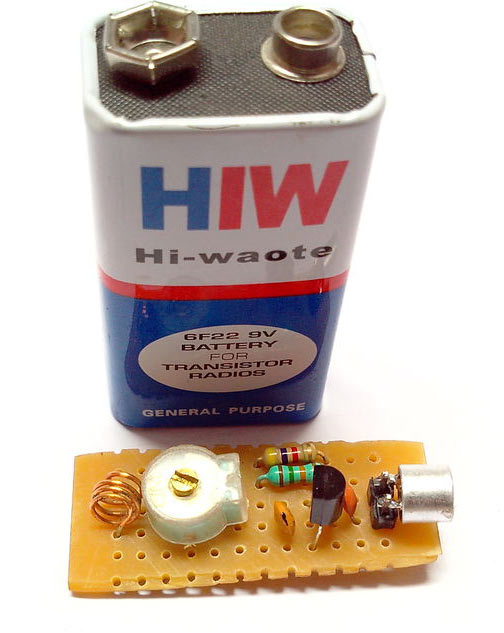
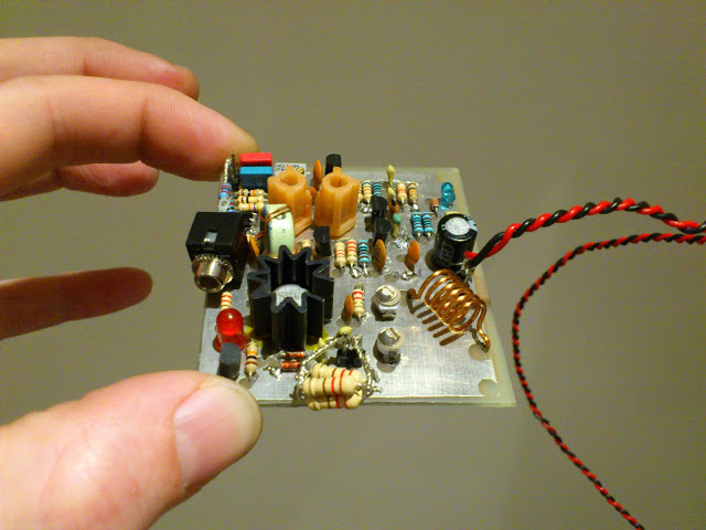
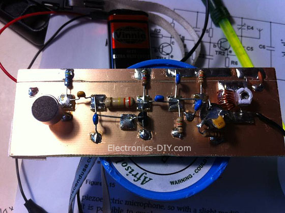
This little 88-108MHz FM transmitter has a range of up to 1 mile in the open. The transmitter consists of three stages. The first stage is an audio pre-amplifier built around 2SC9014 transistor, second stage is an oscillator built using 2SC9018 transistor, and third stage is an RF amplifier built around 2SC9018 transistor. RF amplifier stage increases an output power, range and stability by separating the antenna from the oscillator.
Posted on Monday, February 5, 2024 • Category: FM Transmitters
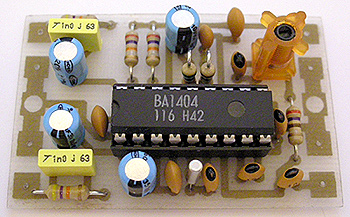
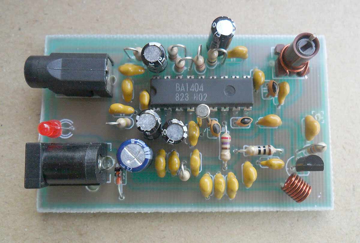
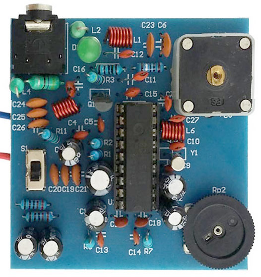
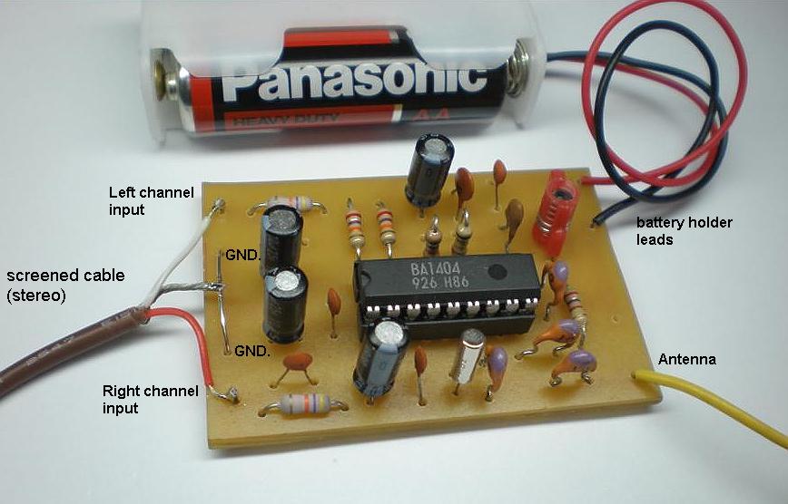
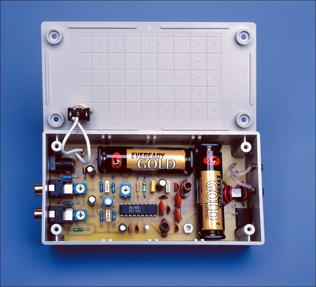
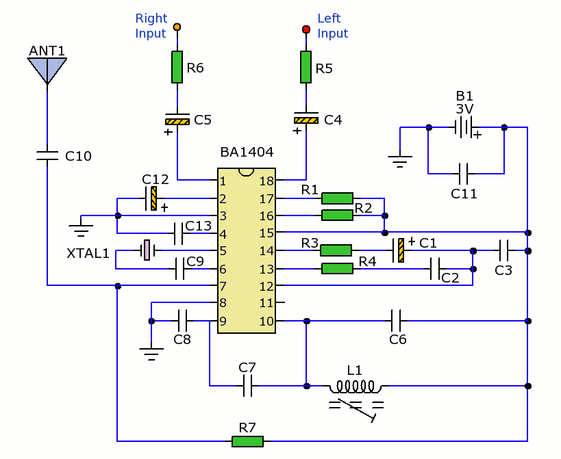
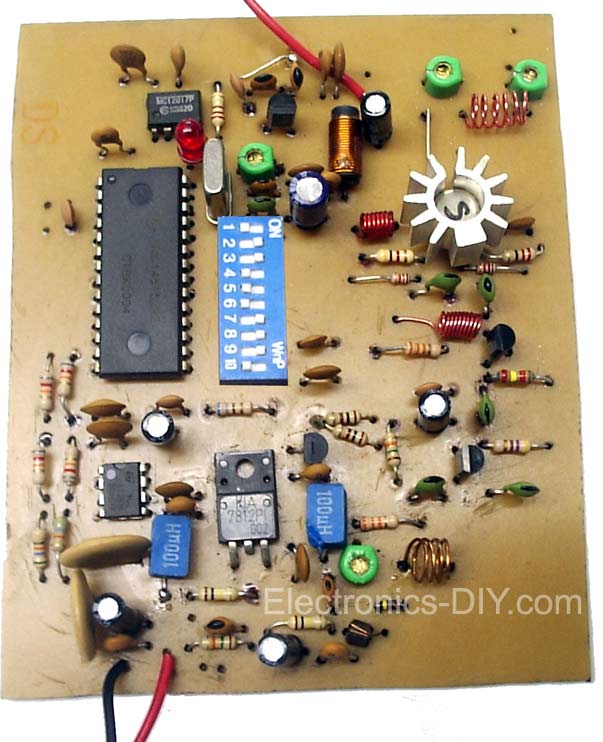
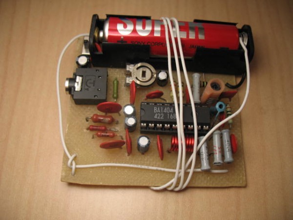
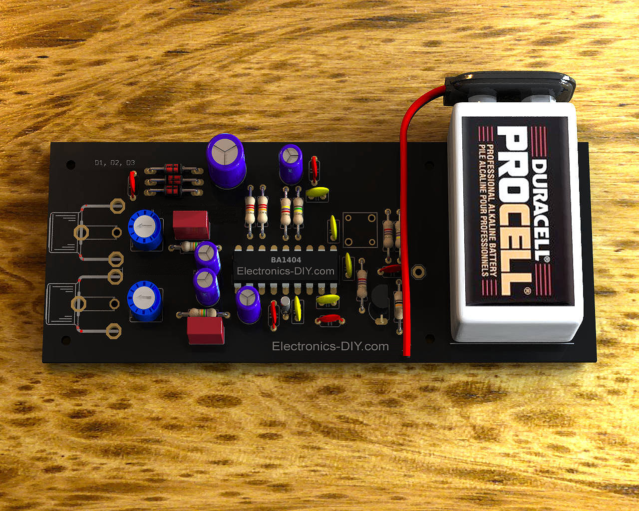
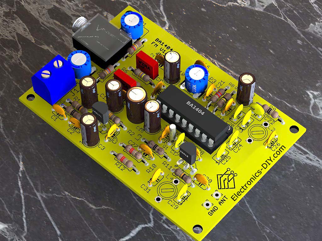 Build your own fairly simple high quality stereo FM transmitter circuit as shown in the photo. The circuit is based on the BA1404 chip from ROHM Semiconductors and S9018 amplifier for extending tansmitter's range. BA1404 is a monolithic FM stereo modulator that has built in stereo modulator, FM modulator, RF amplifier circuits. The FM modulator can be operated from 76 to 108MHz and the power supply for the circuit can be anything between 6 to 12 volts.
Posted on Friday, July 28, 2023 • Category: FM Transmitters
 1 Watt FM Transmitter amplifier with a reasonably balanced design specified to boost a RF frequency in the 88 – 108 MHz spectrum. It may be considered a fairly sensitive configuration when used with quality RF power amplifier transistors, trimmers and inductors. It involves a power amplification factor of 9 to 12 dB (9 to 15 times). At an input power of 0.1W the output may be well over 1W. It's advisable to choose T1 transistor on the basis of the input voltage. For 12V voltage it is recommended to use transistors such as 2N4427, KT920A, KT934A, KT904, BLX65, 2SC1970, BLY87. For 18-24V voltage may may want to use transistors such as 2N3866, 2N3553, KT922A, BLY91, BLX92A. You may also consider using 2N2219 with 12V input voltage however that would only produce an output power of around 0.4W.
Posted on Thursday, January 20, 2022 • Category: FM Transmitters
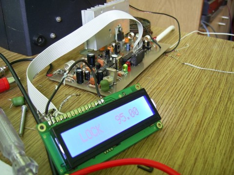
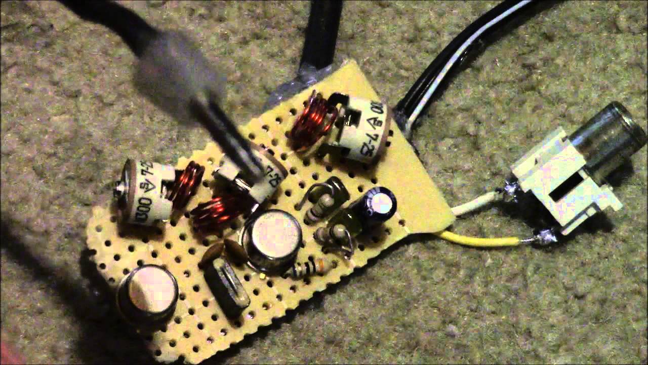
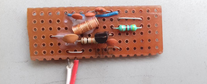
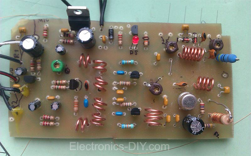
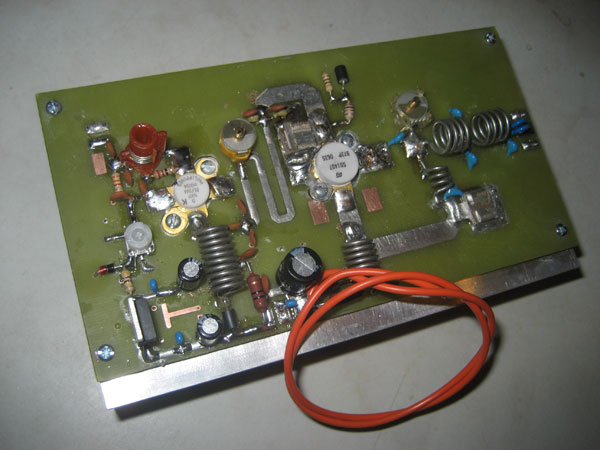
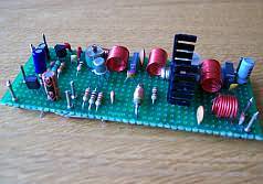
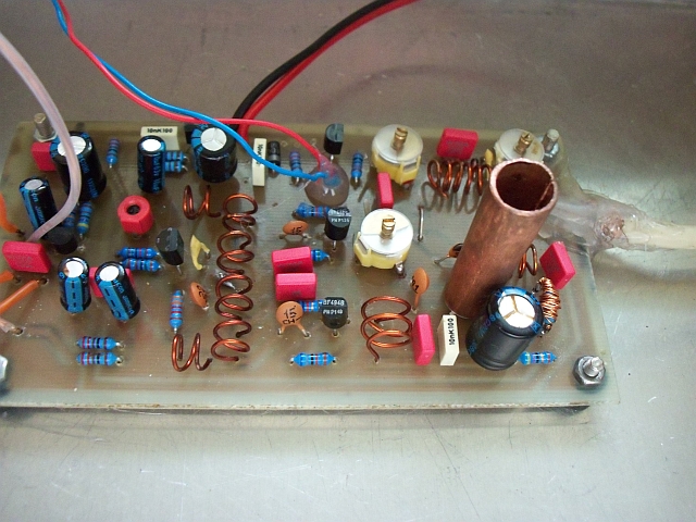 This a build of a well known FM transmitter called Veronica. Transmitter was built on two separate boards. The first board (pictured above) is the Veronica transmitter itself with output power of 600mW when powered by 12V voltage or 1W when powered by 16V voltage. The second board is an RF power amplifier that uses 2SC1971 transistor to amplify Veronica's output signal to around 7 Watts. Although transmitter can be powered with 9-16V voltage, it is recommended that both transmitter and amplifier is powered by 12V voltage as 600mW is an upper limit for driving 2SC1971 transistor.
Posted on Tuesday, January 4, 2022 • Category: FM Transmitters
 I had been fascinated with the idea of making simple stereo encoder for building Stereo FM Transmitter. Not that stereo means much to me away from the computer. I use an FM broadcast transmitter to relay the output of my computers to FM radios in the kitchen, the bedroom, the driveway, and out in the garden. Under those circumstances, I find that mono is plenty, whether it is music or radio programs from over the internet, since I am primarily occupied with something else anyway. When on my hands and knees in the garden, all the way up to my elbows in planting a bush, the music really does not seem any more sweet when its stereo. But that did not stop me from being fascinated with the idea of making a stereo encoder. Stereo always seemed like a lot of circuitry and bother for the slight benefit that came with it. That is, until a few weeks ago.
Posted on Friday, October 1, 2021 • Category: FM Transmitters
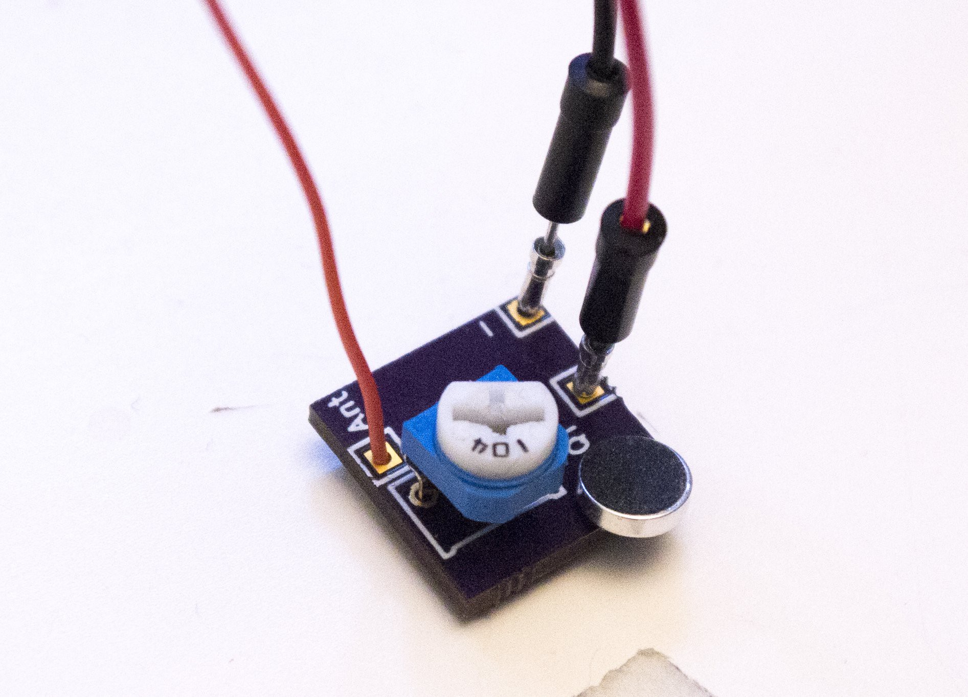
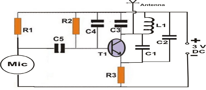
 Ever wondered how come you can just simply tune in to your favorite FM Radio Channel. Moreover, ever had the curiosity of making your own FM Station on a specific frequency? Well if the answer is Yes to any of those questions then you are at the right place!. We are going to look into making small FM Transmitter for Hobby Purposes with a really basic component guide and components that are readily available off the shelf.
Posted on Tuesday, June 29, 2021 • Category: FM Transmitters
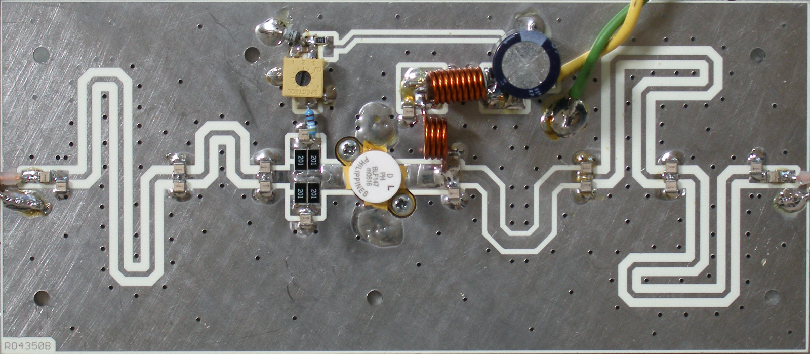 One of the very latest developments here is 150W VHF transmitter amplifier with BLF147 power transistor. Results are very impressive with well over 150W across the band with 10W input and 24 VDC supply. Over 200W is achieved at 28 VDC, and over 250W with a hot bias 4-5A quiescent. PCB is teflon glass board with printed transmission lines and porcelain caps. No external harmonic filter is needed, as the filtering is built into the matching network.
Posted on Monday, April 12, 2021 • Category: FM Transmitters
 There are many applications for an FM transmitter, particularly if it can broadcast in stereo. You can broadcast stereo signals from your CD player or any other source to an FM tuner or radio. This FM Transmitter uses a single BA1404 IC and a few other components. It broadcasts on the 88-108MHz FM band so that it can be received by any standard FM tuner or portable radio. Transmitter runs from a 5V supply and can drive a dipole antenna for improved range.
Posted on Wednesday, February 10, 2021 • Category: FM Transmitters
 This project is the construction of FM transmitter circuit for commercial radio frequencies between 88 MHz and 108 MHz. The transmitter is easy to build and offers good frequency stability through the usage of UA741 oamp. 1Km range can be achieved when powered by 9V battery with 30cm long telescopic antenna.
Posted on Tuesday, November 24, 2020 • Category: FM Transmitters
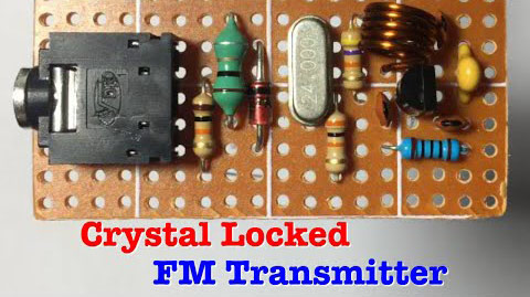 The circuit presented here uses a crystal oscillator and frequency multiplier to generate a highly-stable carrier signal frequency of 96MHz. It can be used to transmit voice or music up to hundred meters. The circuit is built around 9018 transistor, 24MHz crystal, air coil and a few other basic components.
Posted on Tuesday, June 2, 2020 • Category: FM Transmitters
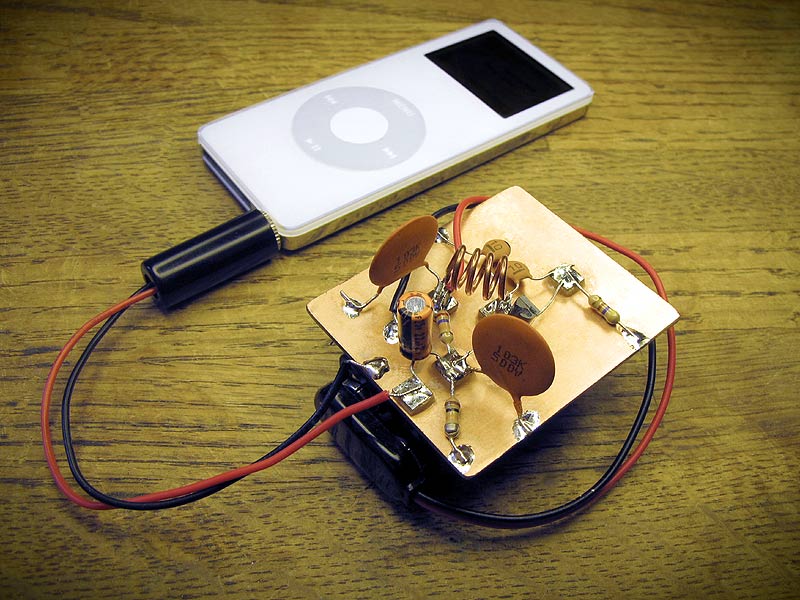
 This is a classic low-cost stereo FM transmitter that can send your signal to a FM receiver within 500 meter range. This transmitter uses the famous BA1404 all-in-one chip and operates from 5v power supply. Stereo channel separation is excellent. You can even use this as a front-end stereo RF signal generator for a large FM transmitter setup; by adding step-by-step RF amplifier. A few inch long copper wire can be soldered at the PCB to use as an antenna. The gang-condenser can be used to adjust frequency output. You can use this with your iPod or other audio source, inside your home or car on in an outdoor garden party or wherever you use.
Posted on Tuesday, April 14, 2020 • Category: FM Transmitters
 This is 1 Watt FM amplifier with a good design that can be used to amplify RF signal of low power FM Transmitters in the 88 – 108 MHz band. It is very sensitive if you use good RF power amplifier transistors, trimmers and coils. It has a power amplification factor of 9 to 12 dB (9 to 15 times). At an input power of 0.1W the output will be 1W. You must choose T1 depending on applied voltage. If you have a 12V power supply then use transistors like: 2N4427, KT920A, KT934A, KT904, BLX65, 2SC1970, BLY87. At 18 to 24V power supply you must use transistors like: 2N3866, 2N3553, KT922A, BLY91, BLX92A. You may use 2N2219 at 12V but you will get maximum output power of 0.4W.
Posted on Monday, March 2, 2020 • Category: FM Transmitters
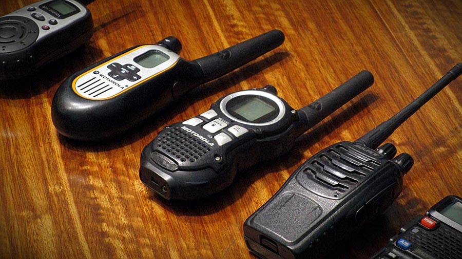 RF projects are always special and I am confident that almost every engineer or enthusiast want to try building a RF project. Because of this we have put together a guide for building a super cool Walkie Talkie project. Walkie Talkie is a half duplex wireless communication device that is capable of establishing communication within short range. Half Duplex means only one user can speak or send his message at a time and communication cannot happen simultaneously. These devices are widely used by Security Personal, Industrial workers and so on. Of course it can make a great toy as well. This guide explains about a Walkie Talkie circuit that allows user to establish communication with another identical device within a range of 30m.
Posted on Tuesday, February 11, 2020 • Category: FM Transmitters
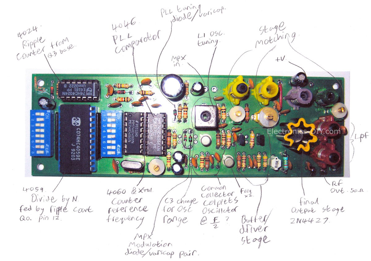
 This is a good quality FM transmitter with 5km range and stable frequency brought by the modified oscillator, which is actually two oscillators built around Q2 and Q3 working at around 50MHz in anti-phase. The output is taken at the two collectors, where the frequencies of the two oscillators combine to form FM signal. This will provide a greater stability than normal single ended oscillators.
Posted on Sunday, February 2, 2020 • Category: FM Transmitters
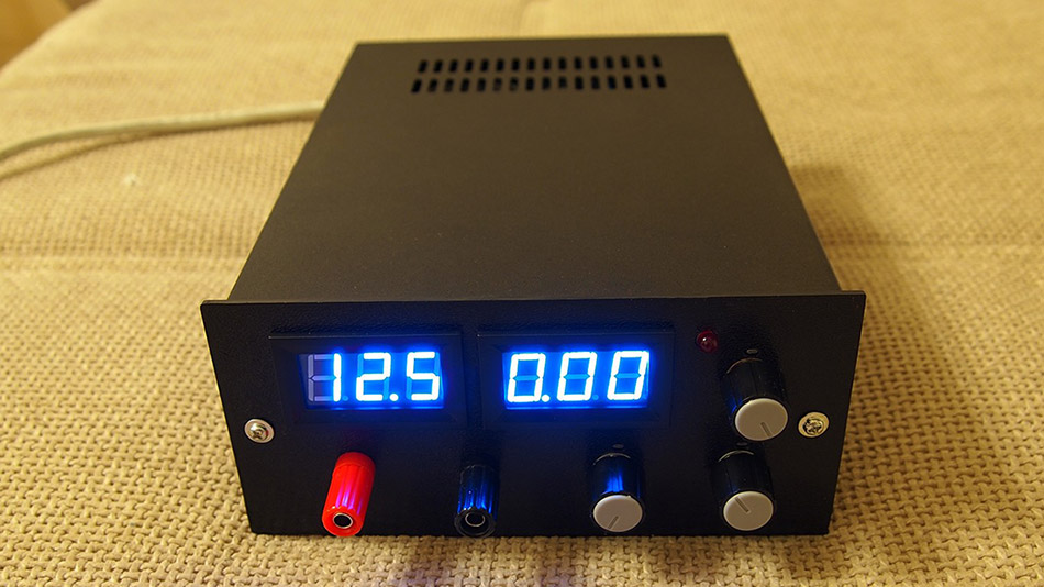 Every laboratory needs a few critical devices, the most important of which is a power supply for powering the projects. But as demand grows and the projects get bigger a professional and adjustable power supply becomes a necessity. Here is an adjustable 50V/5A power supply with a variable output from 0V to 50V and adjustable current limiting from 0A to 5A. Most simple power supplies cant get the output to come down to exactly 0V or 0A. But in this circuit, the differential amplifiers have a negative power supply rail at (-3V), which can pull the output down to exactly zero.
Posted on Wednesday, January 22, 2020 • Category: FM Transmitters
 This tiny FM transmitter can be used for varierty of applications such as monitoring, running your own radio station, etc. It can run on a voltage between 3 and 13 volts, draws 2-3 milliamps and has a theoretical output power of 3 milliamps although you could easily increase that by adding an RF amplifier.
Posted on Tuesday, January 7, 2020 • Category: FM Transmitters
 The above wireless FM transmitter circuit is basically a small RF transmitter built around a single transistor. The circuit functions quite like a Colpitts oscillator incorporating a tank circuit for the generation of the required oscillations. The frequency mainly depends on the positioning and the values of the inductor, C1, C2 and C3. The coil turn distance and diameter may be manipulated a little for optimizing best response over the FM receiver. A small antenna in the form of a 3 inches wire may be attached at the shown point for making the “bug” highly responsive and generates distortion free signals.
Posted on Tuesday, December 10, 2019 • Category: FM Transmitters
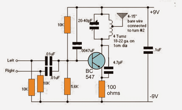 If you want your tiny FM transmitter circuit to transmit music instead of spying or eavesdropping, you would probably find the following design interesting. The proposed FM transmitter will allow combining a stereo input simultaneously from the source so that the info contained inside both the channels get into the air for an optimal reception. The stability of the transmitter is improved by tapping the antenna from one top turn of the coil as shown in the above circuit.
Posted on Monday, July 22, 2019 • Category: FM Transmitters
 Learn to build your own mini FM transmitter. This fun project will show you how to build a mini broadcasting device that can transmit an audio signal up to a quarter mile to any FM receiver. It's easy to build and a good learning experience.
Posted on Tuesday, June 18, 2019 • Category: FM Transmitters
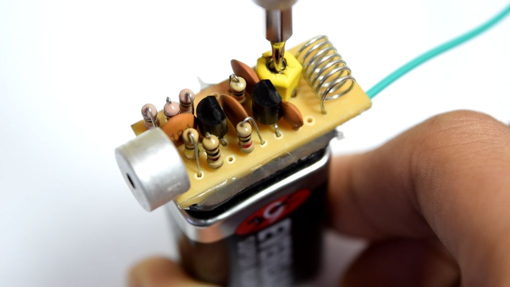
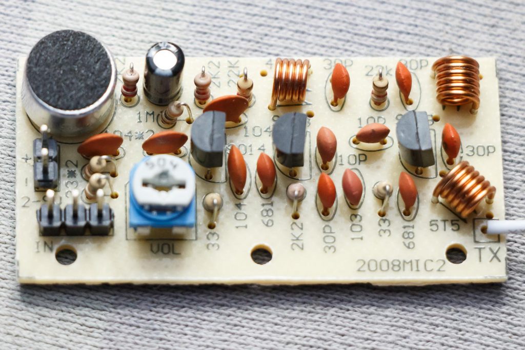 With this three stage transistor transmitter we can create and broadcast our mini radio station. We using S9018 transistor because it can handle very high frequencies, up to and including the VHF band. The first transistor on the left is a microphone audio amplifier for modulation. The gain can be adjusted with the potentiometer. The second transistor is the oscillator with a range of 80 to 103 MHz. The frequency can be changed with the upper coil 4T5 by pulling it slightly apart. The signal from the oscillator is very small, so that still needs to be amplified. The right most transistor is therefore an RF amplifier. This amplifies the signal from the oscillator to feed to the antenna. This transistor also immediately provides more stability, because the oscillator is not directly connected to the antenna.
Posted on Tuesday, June 4, 2019 • Category: FM Transmitters
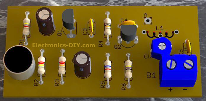
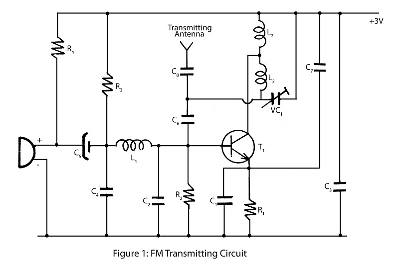
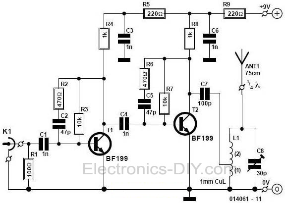
 With a matching antenna, the FM transmitter circuit shown here can transmit signals up to 2 kilometers. The transistor Q1 and Q2 forms a classic high sensitive preamplifier stage. The audio signal to be transmitted is coupled to the base of Q1 through capacitor C2. R1, R3, R4, R6, R5 and R9 are the biasing resistors for the preamplifier stage comprising of Q1 and Q2. Transistor Q3 performs the collective job of oscillator, mixer and final power amplifier. C9 and L1 forms the tank circuit which is essential for creating oscillations. Inductor L2 couples the FM signal to the antenna.
Posted on Friday, February 1, 2019 • Category: FM Transmitters
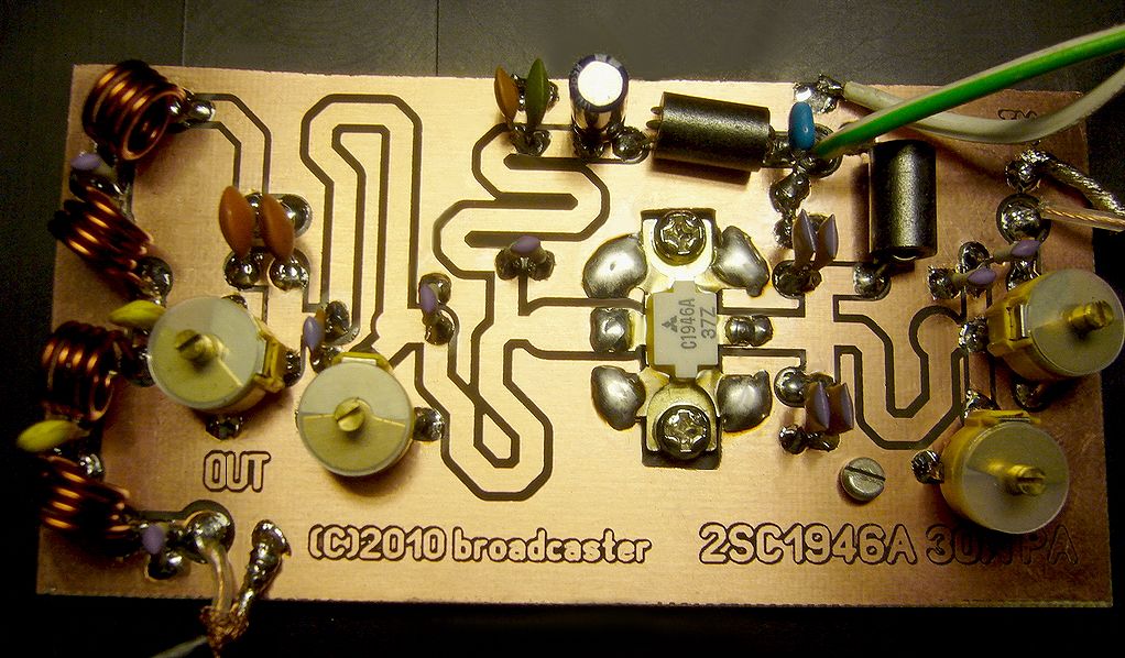 This RF Amplifier designed for FM broadcast using a single 2SC1946 VHF Power Transistor. This 10-30W RF amplifier circuit provides an appropriate power boost with an input of 1-3 watt. Tower are 30 meters high will send signal surrounding air should be around 15 km.
Posted on Tuesday, January 22, 2019 • Category: FM Transmitters
 That small circuit transmitter it is ideal for ready espionage for strip from radio Fm or receiver of VHF. Of course the recreational purpose also exists and the children will adore to have a transmitter that allows to speak for a radio FM placed at distant place and like this pretend the secret agent.
Posted on Wednesday, November 14, 2018 • Category: FM Transmitters
 Powerful microtransmitter that can cover 3km range. To amplify the signal, a 2N3866A transistor is used that can provide up to 1W with gain > 10dB (24Volt). In our case the output power is about 100mW depending on the input power of 10mW and 9V battery power supply. The transistor Q1 must be mounted with a heatsink, the heatsink must have small dimensions (cylindrical) in order not to increase the parasitic capacitance. The trimmer R2 serves to adjust the bias of the transistor, start with the trimmer fully open and close by measuring the current absorbed by the 9V, in my case you get 100mW at the output with a current of 50mA not increase this value as you only increase the absorption by heating the transistor without increasing output power, because the input power is too low. Clearly the 9V battery will be able to provide 50mA only for a few hours, if necessary have greater autonomy should be used a larger battery, but it is no longer a bug but simply an FM transmitter.
Posted on Monday, October 29, 2018 • Category: FM Transmitters
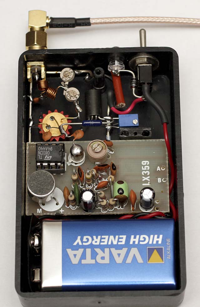
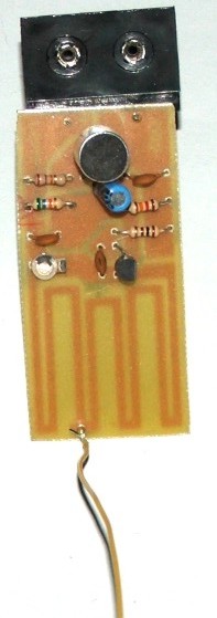
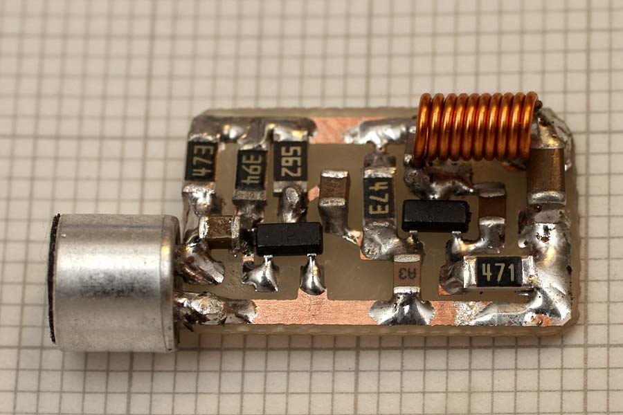 This tiny 88-108Mhz FM transmitter bug measures just 10mm x 17mm in size and as you can see in the photos the biggest components are just the microphone and the battery. You can use a small microphone from an older cell phones, they are small in size and have an excellent sensitivity. For an effective power supply the 9V battery (Duracell) is excellent and allows several hours of battery life, but if you want to have a smaller size it is better to use 2 or 3 lithium cells like the 2032 used in PCs. The circuit works well from 3 to 12V, the maximum range is obtained with 12V and a piece of 40-60cm cable as an antenna.
Posted on Monday, September 10, 2018 • Category: FM Transmitters
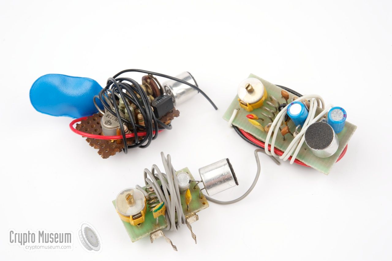 In the mid 1970s large numbers of small FM transmitters, operating in the FM radio broadcast band (88-108 MHz) appeared on the market. It started with a self-build kit from the Danish manufacturer Jostykit that allowed everyone to build a small FM transmitter for a few Euros. Such transmitters generally consist of a single transistor oscillator with a simple resonance circuit, sometimes with an extra transistor that is used as audio pre-amplifier. The image shows a few examples that were available in European electronics shops in the mid 1970s. The transmitter shown here was built in the mid-1970s and measures just 1 x 2 cm. When properly built, it may have a range of several kilometers.
Posted on Wednesday, July 11, 2018 • Category: FM Transmitters
 This is a simple, portable transmitter operating in the 88-108 MHz FM band. You may use it to run your own private neighborhood radio, just replacing the microphone capsule with a male audio jack connected to your pc or MP3 player. You may also use this as a spy transmitter, but be reasonable in that case. It's rated for 1 Watt, so you can listen to it even from a few kilometers, with a good antenna and not too much obstacles in the way.
Posted on Wednesday, May 2, 2018 • Category: FM Transmitters
 FM transmitter circuit projects are indeed quite popular among electronics hobbyists / students. But the frustrating part is most transmitters refuses to work at all, and secondly the internet is full of crappy transmitter circuits. Designing a stable FM transmitter circuit is rather a difficult job, many calculations are involved their. There are also some construction error and component value tolerance. Here you can find a reasonably stable and well tested transmitter that actually works.
Posted on Monday, March 19, 2018 • Category: FM Transmitters
 This FM Transmitter is stable and has output power of 15-18 watts. You don't have to understand the precise working of the transmitter to build it. But some basic information won't harm. A transmitter alone is, as you probably know, is not enough to start your radio station. In the simplest form you need 4 things. First an input device such as an amplifier you also use with your home stereo. You need a regulated power supply. In this case a 14-18 Volts 2.5-3.5 Ampere. One of the most influential things you need is antenna and coax cable. And finally the transmitter itself. Transmitter is divided into two main parts; the oscillator and the amplifier. The oscillator converts electric sound information into electromagnetic waves. The amplifier gives these waves a bigger amplitude.
Posted on Monday, October 16, 2017 • Category: FM Transmitters
 This FM transmitter circuit is a quite fun project for electronics beginners, so here’s a circuit with the 2SC9018 transistor. It uses the 2SC9018 high frequency transistor, based on a different spin of the common base Collpit’s oscillator. The circuit is rather simple, uses only one transistor and few passive components and performs well in terms of frequency stability, almost zero drifting after about 4 hours of continuous operation.
Posted on Monday, August 7, 2017 • Category: FM Transmitters
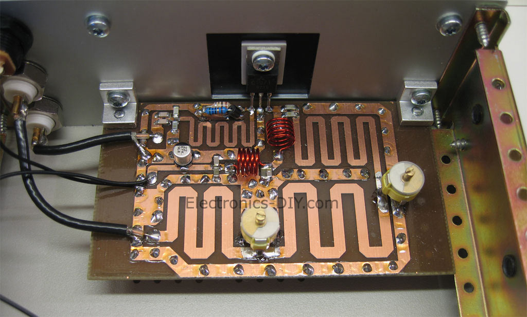
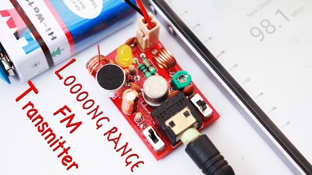
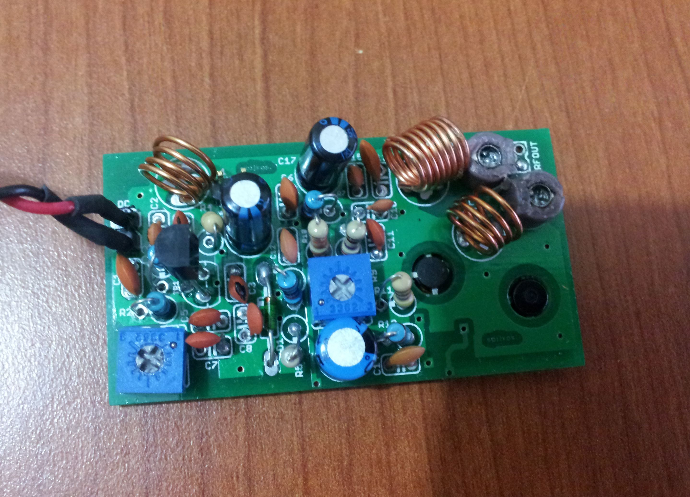
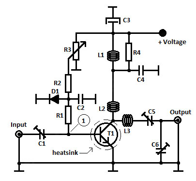
 Here we are presenting a long range FM transmitter that can cover a reasonable distance of 5 kilometers / 3 miles and beyond with a one watt RF power with full circuit details, bill of material and testing procedure. With 12 volt DC it will deliver 1 watt RF power. With Yagi antenna, looking like early days of TV antenna with aluminum pipes at both at transmitter and receiver end looking each other at line of sight distance, the range can be up to 5 km / 3 miles.
Posted on Wednesday, June 21, 2017 • Category: FM Transmitters
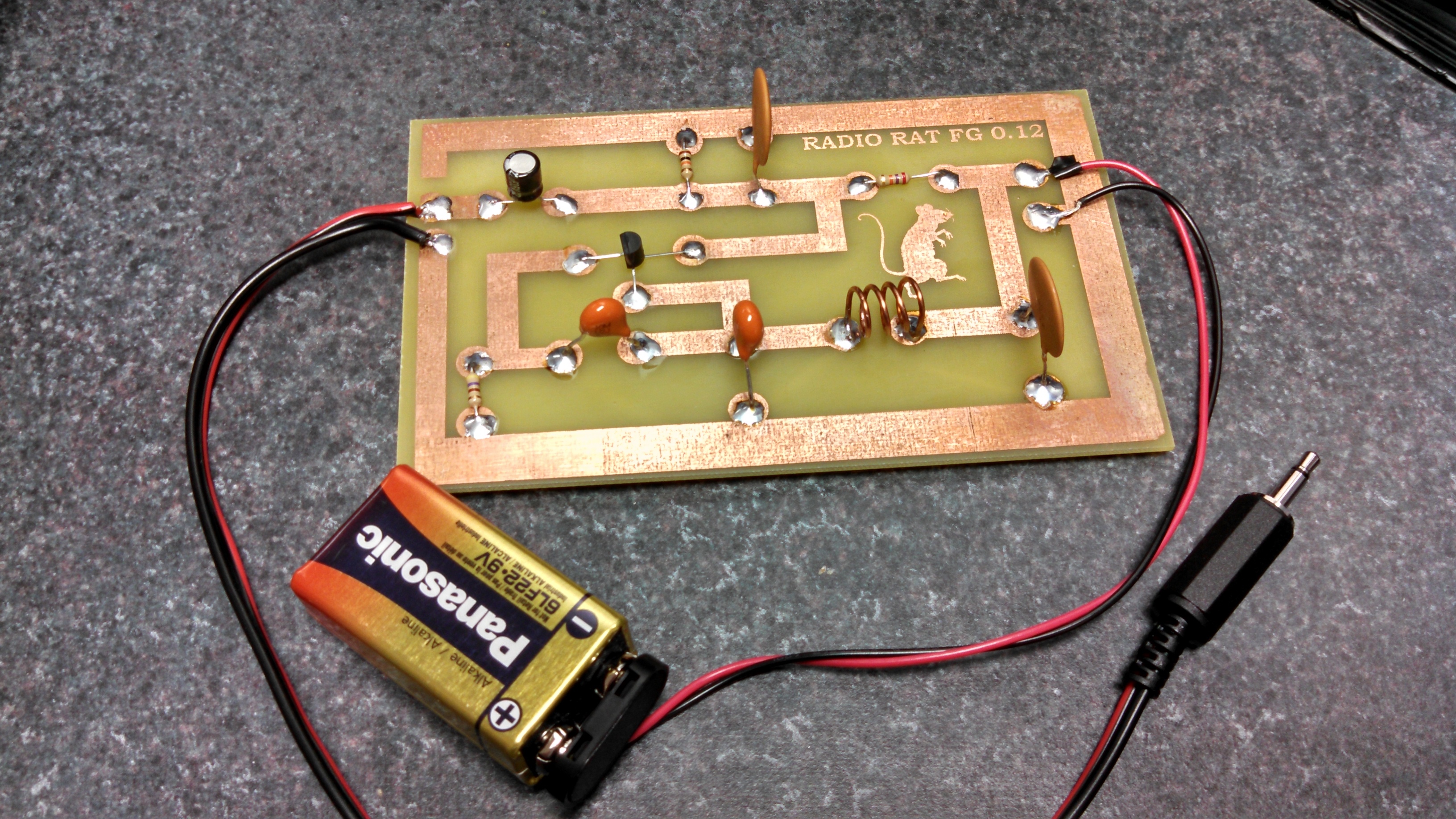
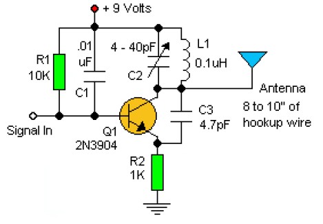
 This circuit is basically an oscillator which runs at around 100 MHz. The most important parts of the oscillator are the transistor Q1 and the tuned circuit, which comprises the inductor Ll and the variable capacitor CV1. When the battery is first connected, a brief surge of current flows from the collector to the emitter of Q1, causing an oscillating (i.e: alternating) current to flow back and forth between Ll and CV1. An oscillating voltage therefore appears at the junction of Ll and CV1. The frequency of the oscillation depends on the values of Ll and CV1, so that varying the value of CV1 tunes the oscillations to the exact frequency required.
Posted on Wednesday, March 22, 2017 • Category: FM Transmitters
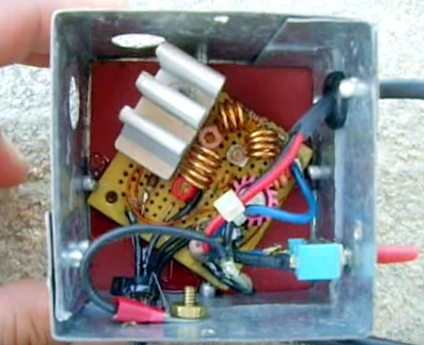 The following is a simple yet powerful 4W FM transmitter which is tunable to 88-108MHz frequency. Connect to your ipod/computer, etc. When this was first made, I only had a 2N2219A on hand, which resulted in a lower RF output. I have since swapped out the transistor for a 2N3866 for full 4W output at around 15VDC supply. In order to achieve a high output level, you will need a well tuned antenna, and a large heatsink to dissipate the heat from T2 transistor.
Transmitter was mounted in metal enclosure and works extremely well.
Posted on Sunday, October 30, 2016 • Category: FM Transmitters
 The above FM transmitter has RF output power of 300 mW and covers more than one kilometer distance. Frequency adjustment is accomplished with MV2105 varactor diode and R7 10K potentiometer. 2SC2538 is a class C 300mW amplifier.
Posted on Monday, October 24, 2016 • Category: FM Transmitters
 High performance low noise 500mW amplifier / booster for all low power FM transmitters such as BA1404, BH1417, BH1415, 433MHz transmitter modules, etc. The amplifier chip is an integrated circuit containing multiple transistor stages and all other parts conveniently within a single small package. Boosting your FM transmitter has never been easier and the output signal can also directly drive 2n4427 or 2n3866 transistors for 1W or 5W of RF output power.
Posted on Friday, October 21, 2016 • Category: FM Transmitters
 The power amplifier boosts 88-108MHZ 1-2W FM transmitter's power to 15 W. It includes multi-level low pass filter and has a high conversion efficiency with strong Yi-wave suppression. With good antena expected transmission coverage is at least 15Km. It uses high power 175 MHZ 4A 25W 2SC1972 RF transistor that must to be mounted to heatsink for proper heat dissipation.
Posted on Friday, June 24, 2016 • Category: FM Transmitters
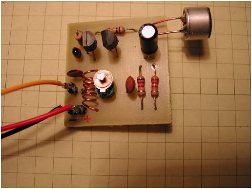
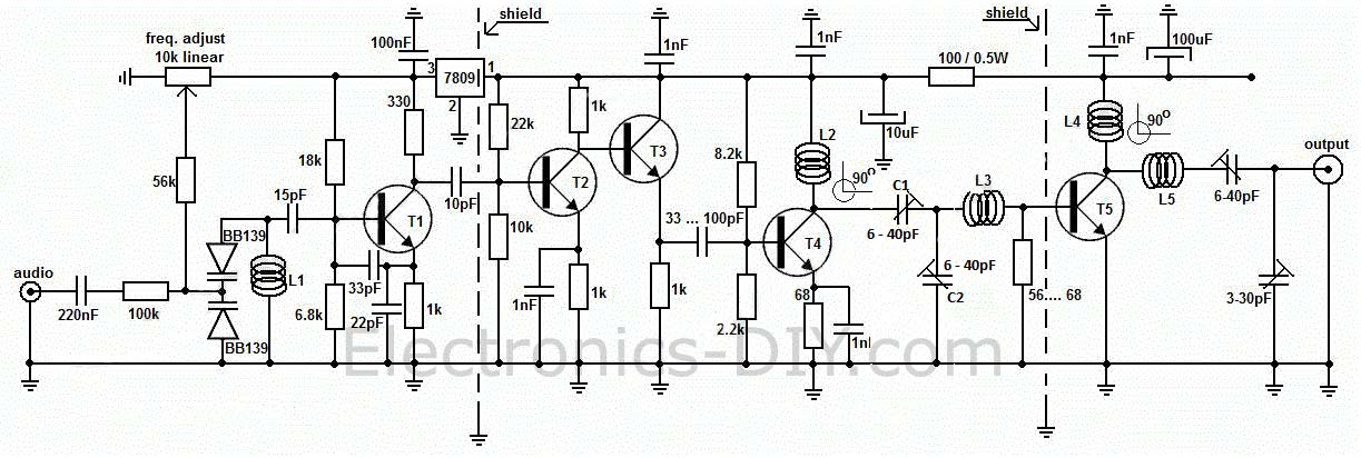
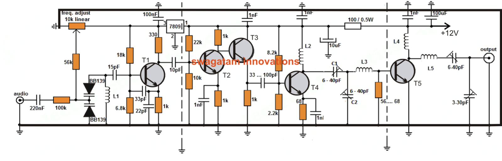 The proposed long range transmitter circuit really is very steady, harmonic free design which you can use with standard fm frequencies between 88 and 108 MHz.
This will likely encompass 5km spectrum (long range). It includes an extremely consistent oscillator for the reason that you employ LM7809 stabilizer that is a 9V stabilized power source for T1 transistor and for frequency realignment that may be reached by means of the 10K linear potentiometer. The output strength of this long range rf transmitter is approximately 1W. Transistor T1 is employed as an oscillator stage to present a small power steady frequency. To fine-tune the freq. apply the 10k linear potentiometer this way: should you moderate, in the direction of ground, the freq. would probably decrease but when you fine-tune it in direction of + it would climb. Essentially the potentiometer is needed just as a flexible power source for the a pair of MV2019 varicap diodes. Both of these diodes function as a changeable capacitor whilst you regulate the pot. By tweaking the diode capacitance the L1 + diodes circuit renders a resonance circuit for T1. Feel free to employ transistors similar to BF199, BF214 however be careful not to use BCs. At this point you don’t receive yet the long range fm wireless transmitter due to the fact that the electric power is fairly reduced, a maximum of 0.5 mW.
Posted on Friday, May 20, 2016 • Category: FM Transmitters
 Pen FM Transmitter bug projects have been very popular. The idea of being able to hide a transmitter in a pen is very appealing. In an effort to reduce the size of this design, we have used surface-mount components. Firstly, the thought of using the coil in the tank circuit for transmitting RF was a little far fetched, but we used it as an example for those who were interested in experimenting with our circuits. Now we have gone back to a conventional antenna, the whip. The whip or straight-line antenna can be coiled, wound longitudinally or folded. The way it is wound makes a big difference to its effectiveness, but when you are limited in space, you have to accept these limitations.
Even though we have used this antenna set up in our previous pen bugs we have considerably improved the circuit to the point were it has low battery consumption, but high RF output. The size of this design has been reduced considerably by using surface-mount components.
Posted on Monday, May 16, 2016 • Category: FM Transmitters
 Three stage FM transmitter with an on board signal booster for increased transmitting range. It broadcasts audio on 76MHz - 110MHz FM frequency via included on board microphone or from MP3 player, Phone, iPod, Computer, Laptop, CD Player, TV, Satellite Receiver via on board 3.5mm connector. It transmit sound with excellent clarity throughout your home, office, yard, camp ground, etc. Transmitter is supplied by 3-12V DC voltage and uses one 2SC9014 and two 2SC9018 low noise RF transistors.
Posted on Saturday, April 16, 2016 • Category: FM Transmitters
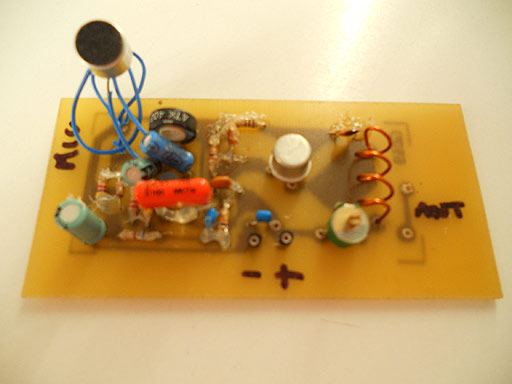
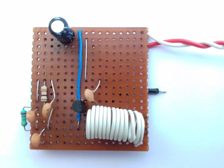
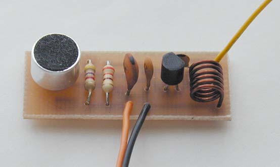
 I found this FM transmitter circuit on the internet, it works very well and it is very simple to build, even for amateurs. I managed to squeeze all the parts on small 1.5 x 2 cm PCB. When using small wire antenna and 3V power the range is 50m. The coil has 10 turns on a 3 mm diameter and is wound with 0.3 mm copper wire. The microphone is an electret type. Transmitting frequency is changed by stretching or compressing the coil. Furthermore, we can change the frequency by changing C2 capacitor (10pF capacitor with a frequency of about 88MHz, with 8.2pF 95Mhz and 6.8pF 104Mhz). Further tuning to the correct frequency is done through the coil. Transmitter can be powered by 3V button battery.
Posted on Sunday, April 3, 2016 • Category: FM Transmitters
 This easy to build transmitter transmits high quality stereo sound from your MP3 player, computer, walkman or discman to any FM radio or car radio. The circuit is designed around the BA1404 single chip FM stereo transmitter from ROHM. The IC requires only a small number of external parts so it is well suited for hobbyist projects. The chip features excellent frequency stability, low power consumption & good channel separation. The transmitting RF frequency can be set by adjusting the coil (Lx). This 2 turn coils is paired with a 39 pF capacitor (Cx) to give a frequency range from 87 MHz - 106 MHz.
Posted on Sunday, March 20, 2016 • Category: FM Transmitters
 This FM VHF transmitter will output approximately 250mW of RF power using a 2N3866 output transistor and can operate between 75MHz and 146MHz. It utilities a variable high gain audio pre-amplifier which can detect voices 40 feet away using an electret microphone. Using a NBFM scanner, ranges over 5KM have been achieved using a 48cm wire antenna. Coils are 22SWG 7mm air core. L1 and L2 should be 6 turns for 75MHz to 85MHz, 4 turns for 85MHz to 100MHz and 3 turns for 100 to 146MHz. For frequencies over 100MHz the Crystal will be higher than 20MHz hence the base emitter capacitor should be 47pF. L3 is a 4.7uH choke. It is ideal to tune up this circuit using a wave detector meter placed a few inches away from the transmitter.
Posted on Tuesday, February 23, 2016 • Category: FM Transmitters
 Have you ever wanted to broadcast your own radio station within your neighborhood? This small and simple 87-108MHz FM transmitter is the toy that geeks have always wanted. This tutorial includes the PCB layout and the schematics. It has a range of up to 1/4 mile or more. It's great for room monitoring, baby listening and nature research.
Posted on Wednesday, February 3, 2016 • Category: FM Transmitters
 FM transmitters can be complicated to build, but not this one — this iPod FM transmitter about the easiest you can possibly make. And though the science of radio is well understood, there’s a magical, emotional quality about it that we don’t often stop to appreciate. You will not forget the first time you pick up a transmission broadcast from a device you soldered together, yourself, from a few bits of copper, carbon, plastic, and wire.
Posted on Monday, January 18, 2016 • Category: FM Transmitters
 The circuit is a simple 88-108 MHz VHF FM transmitter circuit. It is basically a VHF Colpitts oscillator capable of transmitting sound or music to any standard FM receiver. The circuit is powered by 9V battery which makes it easily portable. It also has a capacitor microphone which picks up very weak sound signals. The output frequency can be easily adjusted by potentiometer thanks to onboard MV2109 varicap diode and the frequency stability is quite good. The range of this transmitter is 100 meters.
Posted on Friday, December 18, 2015 • Category: FM Transmitters
 This simple circuit is based on BA1404 FM Transmitter, works with two AA batteries and can drive a 300W dipole antenna for improved range. There are many applications for an FM transmitter, particularly if it can broadcast in stereo. You can broadcast stereo signals from your CD player or any other source to an FM tuner or radio. The transmitter uses a single IC and a few other components. It broadcasts on the FM band (88-108MHz) so that it can be received by any standard FM tuner or portable radio.
Posted on Thursday, December 3, 2015 • Category: FM Transmitters
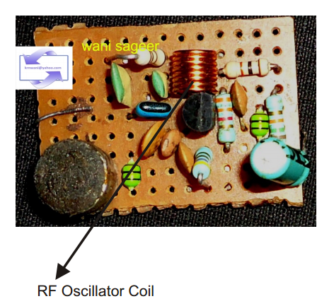
 This basic RF oscillator circuit is easy to build and the components are not critical. Most of them can be found in your junk parts box. The circuit operated with 9V DC power supply. The L1 antenna coil can be made by close winding 8 to 10 turns of 22 gauge insulted magnetic wire around 1/4 inch form such as a pencil. You can experiment with the size of the coil and the number of turns to see how it affects the frequency and signal output of the oscillator. You should be able to pick up its signal with standard FM radio receiver. Signal In to any audio player through 0.1uF capacitor.
Posted on Thursday, November 26, 2015 • Category: FM Transmitters
 This 7 Watt FM Transmitter was originally a 200mW unit, without the universal power stage added. Together with the power amp 2SC1971 / MRF237 / NTE342 it then became a 7W unit. I used this transmitter with a half-wave open-end dipole in a vertical position 50 feet above ground. Together with about 70 feet of coax, this transmitter delivered great audio at a distance of 10 miles ... overall distance was 17 miles, but the audio signal was weak. I had no equipment, other than a watt meter to measure it's power and a digital FM tuner with a 5-LED Signal Strength Bargraph display to use as capturing the main oscillating frequency, which was right at 87.5 MHz. This circuit worked well for me, as I had experimented with it for nearly a year. Of course, one would be better off with more equipment than I have had to capture the main oscillating frequency. That was, by far, one of the hardest things to capture. It was thru trial and error, with the FM tuner, in finally finding out how to grab the right frequency. When I finally did get used to find out where my 'main' frequency was, the unit performed extremely well. Like I had said above, right at 10 miles, the unit was at its best giving clear audible audio into the speakers of my car. With the transmitting antenna at 50 feet above ground, I decided to see how well I could receive the transmitter signal from an overpass than is exactly 15 miles from the transmitter. When I got to the top of the overpass in my car, the audio signal came in as 'clear as a bell'. I now understand what is meant when one says FM signal travels best in a line of sight. Well, being on that overpass, if I had a strong telescope with me, I am sure I could see the 50 foot antenna in my oak tree. So with the overpass being right around 50 feet in height also, the transmitter surpassed my judgement call on its signal. I surrender this circuit to anyone who likes to experiment in things like this. Enjoy!
Posted on Friday, September 25, 2015 • Category: FM Transmitters
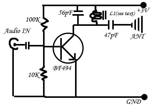 This is the most simple and cheap FM transmitter you can ever find. This circuit is really cool. This runs at very low voltage, by a CR2025 3V battery, current consumption is also low.And the total size of this FM transmitter (including battery, excluding antenna) is less than that of a matchbox. The circuit has a central RF oscillator NPN transistor BF494 (substitute: BF199). A coil takes care of the output frequency. It consists of 36SWG wire 2.5 turns only in 5mm diameter ferrite rod. Keep the circuit as small as possible. Try to use no wires in the main functional area (transistor and coil). The input from the audio output of computer / PMP / mobile is given to the biased base of the transistor. The transistor gives a RF humming accordingly to the audio input, and the FM wave is spread by the external antenna. By using a standard TV antenna, the range of this transmitter can go up to 1KM radius, using small (15-20cm) Ariel, it can work up to around 50M range. This circuit is most suitable for miniature FM transmitter for use in computer, mobile etc to send music to home theater system without wires, and in homemade wireless walky-talkies.
Posted on Thursday, July 2, 2015 • Category: FM Transmitters
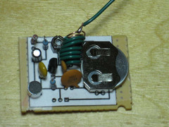 This is the most simple and cheap FM transmitter you can ever find. It's powered by CR2025 3V battery and current consumption is very low. The total size of this FM transmitter is less than that of a matchbox. The circuit has a central RF oscillator NPN transistor BF494. A coil takes care of the output frequency. The coil consists of 36SWG wire 2.5 turns in 5mm diameter ferrite rod. Keep the circuit as small as possible. By using a standard TV antenna, the range of this transmitter can go up to 1KM radius, using small 15-20cm wire, it can work up to around 50M range. This circuit is most suitable for miniature FM transmitter for use in computer, mobile etc to send music to home theater system without wires, and in homemade wireless walky-talkies.
Posted on Thursday, May 28, 2015 • Category: FM Transmitters
 This simple transmitter allows you to broadcast on FM radio band 87.5 - 108 MHz. It consists of a simple oscillator with silicon planar RF PNP transistor. Directly to the oscillator an antenna is connected. Due to the large amplitude of RF voltage is sufficient antenna length of about 5-10 cm. I used insulated 7cm long copper wire 1mm diameter. I eliminated the tuning capacitor, which is usual for most bugs and miniature transmitters, because this greatly complicates the tuning. From my own experience I know that if you get closer to such capacitor, the operating frequency is changed. That's why I chose to use the voltage tuning using the Voltage Controlled Oscillator (VCO). Instead of tuning capacitor the varicap (capacitance diode) is used, which changes its capacity by changing the reverse DC voltage. We can tune the operating frequency by changing the DC voltage using the trimmer P1. Varicap also provides frequency modulation.
Posted on Sunday, May 24, 2015 • Category: FM Transmitters
 This simple 400mW transmitter broadcasts audio on 87.5 - 108 MHz FM radio band. With good dipole antenna transmission range up to 4km is possible. Frequency is selected by adjusting R1 potentiometer. Transmitter should be powered by regulated 12-14V power supply with at least 100mA current rating.
Posted on Thursday, April 23, 2015 • Category: FM Transmitters
 FM transmitters can be complicated to build, but not this one it’s about the easiest you can possibly make. And though the science of radio is well understood, there’s a magical, emotional quality about it that we don’t often stop to appreciate. You will not forget the first time you pick up a transmission broadcast from a device you soldered together, yourself, from a few bits of copper, carbon, plastic, and wire.
Posted on Thursday, March 12, 2015 • Category: FM Transmitters
 This is a small stereo FM transmitter. Output can be tuned from 88 to 108Mhz and the transmitter can be battery powered or be used with presented low voltage power supply. This circuit is based on the Rhom BA1404 datasheet. The maximum voltage should not exceed 3V. The IC can be driven from a 7805 Regulator with a couple of 1N4001 diodes to reduce the supply voltage to about 2.8 Volts. RF output power is typically 500mW but range depends upon antenna coupling and efficiency, environment and size of antenna. A small telescopic whip has an expected range of at leaset 100 metres or more.
Posted on Tuesday, December 30, 2014 • Category: FM Transmitters
 Here is a simple 76-110MHz FM transmitter that can transmit your voice or audio over an ordinary FM radio within the FM broadcast band. It can transmit both voice using microphone and music from any music player. Frequency is changed by adjusting 5.5 turn inductor coil. Transmitter is powered by 9V battery or 3V-9V power adapter. Transmission range is 100 meters but can be increased with better antenna or RF amplifier.
Posted on Wednesday, December 10, 2014 • Category: FM Transmitters
 FM transmitters can be complicated to build, but not this one. It’s about the easiest you can possibly make. And though the science of radio is well understood, there’s a magical, emotional quality about it that we don’t often stop to appreciate. You will not forget the first time you pick up a transmission broadcast from a device you soldered together, yourself, from a few bits of copper, carbon, plastic, and wire.
Posted on Tuesday, August 26, 2014 • Category: FM Transmitters
 Presented FM transmitter is built around low power PLL transmitter and amplifier that boosts its signal all the way up to 6 Watts. The signal is amplified by three RF stages of amplification. In the first and second stages of the transmitter one of the best driver transistors were used 2SC2053. You can use the other transistors but only up to 500mW of power. In the third stage 2SC1971 RF transistor was used to achieve 6W of power. For making any RF transmitter circuit at least two meters are necessary, one is frequency counter and the other is RF field strength meter for which the schematic is provided.
Posted on Sunday, August 3, 2014 • Category: FM Transmitters
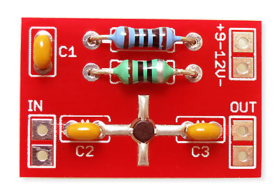
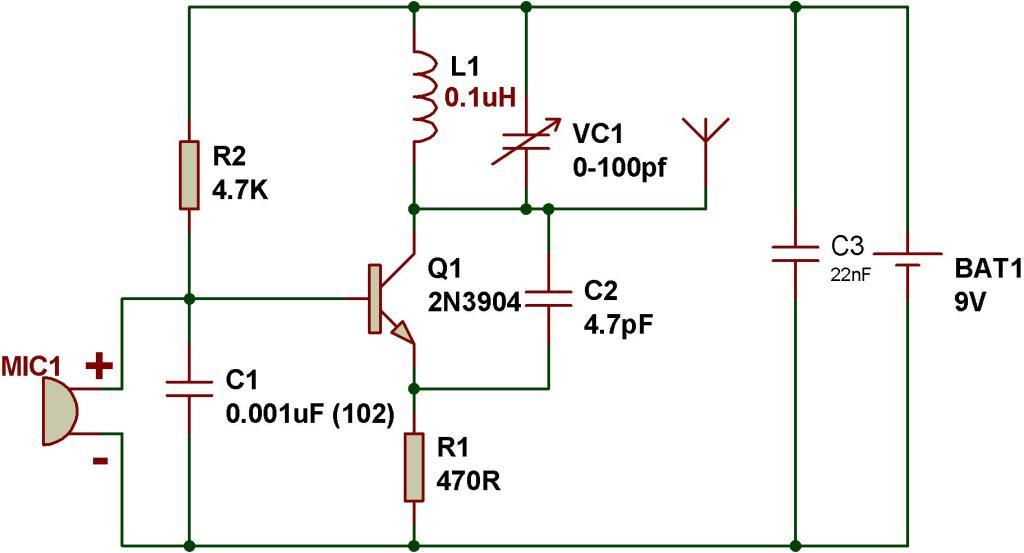
 The figure shows a schematic of an easy to build FM transmitter circuit. Mostly all FM transmitter circuits you will find online or in books require some kind of hand build inductor/coil and after building the transmitter you have to adjust that coil and trimmer capacitor a little to adjust the transmitter to transmit on your desired frequency.
If you are looking for an easy or simple FM transmitter circuit in which you don't have to make a coil with your hand then the circuit given here is ideal for you. The circuit is using a ready made 1uH inductor which can be purchased from an electronic components store. These inductors are mostly look like resistors. The circuit also does not require a trimmer capacitor, because we have used a fixed value of 39pF capacitor in the place of trimmer capacitor. We have already calculated and used the values of coil and capacitors of oscillator to broadcast on FM band, so you don't have to do any further adjustments and tuning after building the circuit. The circuit can be operated with 9 to 12 volt DC. For antenna use a 12 inch wire or for maximum range use a 30 inch wire and make it vertical.
Posted on Friday, June 27, 2014 • Category: FM Transmitters
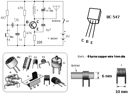
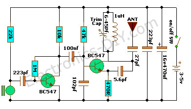
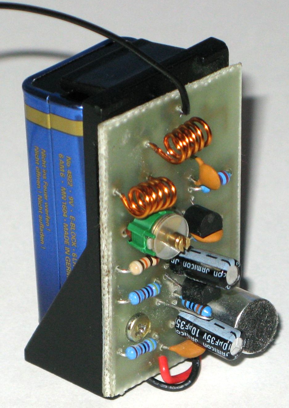
 Here's how to build your own mini FM transmitter. It transmits FM waves so you could easily receive the signals on your mobile phone, radios, etc. As the name and the picture indicates it is very small and is approximately the size of a 9v battery clip. With this FM transmitter you could start your own mini FM station. The circuit uses BC547 transistor to amplify the signal and then frequency modulate it. It uses "frequency modulation" most commonly known as FM, the same principal to transmit audio signals captured by the microphone.
Posted on Sunday, June 15, 2014 • Category: FM Transmitters
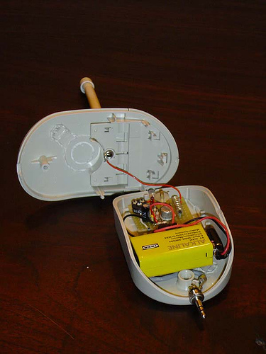
 This small phone transmitter will transmit a phone conversation to an FM radio on the 88-108MHz band. It uses energy from the phone line to transmit the signal about 100 meters away. It uses the phone wire as the antenna and is activated when the phone is picked up. Transmitter components are mounted on a small PC board. PC layout is included.
Posted on Friday, June 6, 2014 • Category: FM Transmitters
 This classic walkie talkie consists of both 27MHz transmitter and receiver all in one circuit. Nearly all the components in the 4-transistor circuit are used for both transmitting and receiving making it simple to build and economical at the same time. The frequency-generating stage only needs 27MHz crystal to be removed and it becomes a receiver. Next is a three transistor audio amplifier with very high gain. The first transistor is a pre-amplifier and the next two are wired as a super-alpha pair, commonly called a Darlington pair to drive the speaker that is also used as a microphone. The use of telescopic antenna will provide better reception and transmitting range. Use two identical walkie talkie circuits for two way communication.
Posted on Friday, May 16, 2014 • Category: FM Transmitters
 This is a VCO FM Transmitter. With good antenna (dipole placed outdoor and high) the transmitter has very good coverage range about 500 meters, the maximal coverage range is up to 4 km. To calibrate for maximum power connect 6 V / 0,1 light bulb to the output and use R1 to tune the right frequency, adjust L1 coil if necesary. Then use C14 and C15 to adjust the highest power (the highest light of the bulb). Then you can connect antenna and audio signal. Adjust R2 until the audio sounds as loud as the other stations.
Posted on Thursday, May 15, 2014 • Category: FM Transmitters
 This is a 1 Watt FM Transmitter amplifier with a good design that can be used to amplify a RF signal in the 88 – 108 MHz band. It is very sensitive if you use good RF power amplifier transistors, trimmers and coils. It has a power amplification factor of 9 to 12 dB (9 to 15 times). At an input power of 0.1W the output will be 1W. You must choose T1 transistor depending on applied voltage. If you have a 12V power supply then use transistors like: 2N4427, KT920A, KT934A, KT904, BLX65, 2SC1970, BLY87. At 18 to 24V power supply you must use transistors like: 2N3866, 2N3553, KT922A, BLY91, BLX92A. You may use 2N2219 at 12V but you will get an output power of 0.4W maximum.
Posted on Tuesday, February 18, 2014 • Category: FM Transmitters
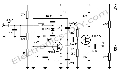 Here's FM transmitter for commercial FM band that provides 18 watts of power. Since the electronic diagram is too large we decided to divide it into two parts. The first part is the actual FM transmitter while the second part is 18W RF amplifier. The circuit should be built on an epoxy printed circuit board with the upper face components reserved for interconnecting tracks and the bottom solder to the ground plane. If powered by 14V and 2.5A transmitter outputs 15W of power, whereas 18V and 3.5A will provide 18W. BB110 variable capacitor connected to the collector of transistor BF199 adjusts the transmission frequency of the circuit. 2K2 potentiometer serves as fine tuning. Once the output frequency is adjusted amplifier variable capacitors must be adjusted for maximum output power one stage at a time. All adjustments must be made with 50 Ohm dummy load connected to the output of transmitter.
Posted on Sunday, December 29, 2013 • Category: FM Transmitters
 Veronica 1W FM transmitter is an easy to build transmitter. Veronica is also known for frequency stability, clean FM signal and uses no integrated circuit. The Veronica oscillator is actually formed from 2 oscillators which operates somewhere around 50 MHz in anti phase and the 2 signals are combined to form 100MHz FM radio signal. This kind of circuit design is stable and is amplified up to 1W by 2n4427 transistor. Veronica transmitter is equipped with a mini-mixer and so you may forget an external mixer. This consist from T1 transistor which amplifies the microphone signal before it is combined with cd-player audio or PC signal. R1 and R2 are potentiometers (variable resistors) used to adjust the audio level. The component between R8 and C21 represents the oscillator wich generates radio signal. D1 is a varicap diode (like a variable capacitor or trimmer) controlled by audio signal. C12, C13 and L1 determines the frequency.
Posted on Wednesday, December 18, 2013 • Category: FM Transmitters
 Following 1W PLL transmitter exciter provides stable, low noise operation. Transmitter uses a PLL frequency synthesizer built with MC145152 which covers the FM band in 100kHz steps. The VCO uses MV2109 varicap diode to automatically tune to selected frequency via SW1 dip switch. output stage uses 2N4417 RF power transistor and provides 1W of RF power. With good antenna expected transmission range is 2km. Transmitter may be built on a double sided PCB, with top side copper left mostly undisturbed as a ground plane. The copper is removed only around non-grounded pins. The ground connections can be soldered on the top side, so it’s not necessary to have plated-through holes.
Posted on Thursday, December 12, 2013 • Category: FM Transmitters
 Here is a very interesting and simple FM transmitter used to transmit audio in the wide range up to 100M using only one transistor. The entire circuit of FM transmitter is divided into three major stages oscillator, modulator and amplifier. The transmitting frequency of 88-108 MHz is generated by adjusting VC1. The input audio generated by microphone is changed into electric signal and is given to base of transistor T1. Transistor T1 is used as oscillator which oscillates the frequency of 88-108 MHz. The oscillated frequency depends upon the value R2, C2, L2 and L3. Transmitted audio from FM transmitter circuit can be received by standard FM receiver.
Posted on Thursday, November 21, 2013 • Category: FM Transmitters
 This is simple FM transmitter for FM broadcast band in 88-108 MHz. BC 549 is small signal transistor for wide applications, but usually for AF. You can build simple FM transmitter with one BC549 transistor and several other component parts. Simple FM transmitter with only one transistor is often called “bug”. This project is suitable for beginners in radio amateur, education, or hobbies. As an antenna you can connect 150cm of copper wire.
Posted on Wednesday, October 16, 2013 • Category: FM Transmitters
 A simple MP3 FM transmitter circuit shown here can be built easily in few minutes if all parts are available to you. All the components used in this transmitter circuit are general purpose and low cost. The circuit will work as a best FM transmitter for simply broadcasting your music around your house and yard, and can be used to broadcast the output of any equipment like mp3 player, ipod, satellite, etc.
Posted on Monday, September 23, 2013 • Category: FM Transmitters
 This is a 1 Watt PLL FM broadcast transmitter. The RF output varies from 500mW to about 1.2W depending on the frequency selected and RF output transistor used. Motorola 2N4427 always seems to work well. Transmitter uses CMOS PLL VCO that prevents the frequency drifts. The frequency is selected via DIP switches. The transmitter is supplied by 12V DC and can also be powered from the battery.
Posted on Friday, September 13, 2013 • Category: FM Transmitters
 This FM transmitter is about the simplest and most basic FM transmitter it is possible to build and have a useful
transmitting range. It is surprisingly powerful despite its small component count and 3V operating voltage. It will
easily penetrate over three floors of an apartment building and go over 300 meters in the open air. The circuit
we use is based on a proven Australian design. It may be tuned anywhere in the FM band. Or it may be tuned
outside the commercial M band for greater privacy. (Of course this means you must modify your FM radio to
be able to receive the transmission or have a broad-band FM receiver.) The output power of this FM Tx is below
the legal limits of many countries (eg, USA and Australia). However, some countries may ban ALL wireless transmissions without a license. It is the responsibility of the builder to check the legal requirements for the operation of this circuit and to obey them.
Posted on Sunday, September 1, 2013 • Category: FM Transmitters
 This portable FM Transmitter is easy to build. I have used a pair of BC548 transistors in this circuit. Although not strictly RF transistors, they still give good range. Transmitter is powered by 9V battery. The coil L1 consists of 7 turns on a quarter inch plastic former with a tuning slug. The tuning slug is adjusted to tune the transmitter. Actual range on my prototype tuned from 70MHz to around 120MHz. The aerial is a few inches of wire. Lengths of antenna wire should be 1 - 2 feet. The circuit is basically a radio frequency (RF) oscillator that operates around 70-120 MHz. Audio from audio jack is fed into the audio amplifier stage built around the first transistor. Output from the collector is fed into the base of the second transistor where it modulates the resonant frequency of the tank circuit by varying the junction capacitance of the transistor. Junction capacitance is a function of the potential difference applied to the base of the transistor. The tank circuit is connected in a Colpitts oscillator circuit.
Posted on Friday, July 19, 2013 • Category: FM Transmitters
 This circuit provides an FM modulated signal with an output power of around 500mW. The input microphone pre-amp is built around a couple of 2N3904 transistors (Q1/Q2), and audio gain is limited by the 5k preset trim potentiometer. The oscillator is a colpitt stage, frequency of oscillation governed by the tank circuit made from two 5pF ceramic capacitors and the L2 inductor. The output stage operates as a 'Class D' amplifier, no direct bias is applied but the RF signal developed across the 3.9uH inductor is sufficient to drive this stage. The emitter resistor and 1k base resistor prevent instability and thermal runaway in this stage.
Posted on Sunday, May 19, 2013 • Category: FM Transmitters
 This low power fm transmitter is designed to use an input from another sound source and transmits on the commercial FM band. This low power fm radio transmitter it is actually quite powerful.
The first stage is the oscillator, and is tuned with the variable capacitor. Select an unused frequency, and carefully adjust C3 until the background noise is removed.
Posted on Saturday, May 11, 2013 • Category: FM Transmitters
 This article shows you how to build a very simple FM transmitter from thirteen components, a Printed Circuit Board (PCB) and a 9v battery.
This project was designed to be mounted on a PCB, however you don’t have to. You could construct the project on Vero board (strip board) or any other 0.1” pitch style of project board. If you just want to experiment with this circuit, you don’t even need a board; you can just solder the component s together and let the completed project just rest on the work top. No matter which style you choose, try to keep all component leads nice and short.
You could also make the PCB much smaller than the one shown here which is approx. 3 cm square. This is a good size to keep the unit small but nicer to work on for beginners. If you wanted to make one really small, you could use all SMT parts.
Posted on Tuesday, April 16, 2013 • Category: FM Transmitters
 Long range, very stable, harmonic free, FM transmitter circuit which can be used for FM frequencies between 88 and 108 MHz. With good antenna transmitter can cover 5km range. It has a very stable oscillator because it uses LM7809 voltage regulator which is a 9V stabilized power supply for T1 transistor. Frequency adjustment is achieved by using the 10K linear potentiometer. The output power of this long range RF transmitter is around 1W but can be higher if you use transistors like KT920A, BLX65, BLY81, 2N3553, 2SC1970 or 2SC1971.
Posted on Friday, April 12, 2013 • Category: FM Transmitters
 Building two stage 40 Watt FM Transmitter Amplifier. RF input power should be between 0.5 and 1 watt. Amplifier is powered by 28V power supply. The diagram shows a 2N3375 driving a 2N5643 but there are many other transistors that will work. I used these two transistors just because they were cheap at the time. If any of the variable capacitors are at full capacitance you can pad them out with a fixed ceramic capacitor of suitable value. Extra capacitance also might be needed on the base of the transistors (i had to add 3 100pF capacitors on the base of the 2N5643). The transistors are bolted to a piece of right angle aluminum which is fixed to the metal chassis to dissipate heat effectively.
Posted on Saturday, March 30, 2013 • Category: FM Transmitters
 This is 150W FM transmitter amplifier for 88-108MHz band. The amplifier has two stages using BLF244 mosfet transistor for the first stage which requires 0.5 - 1Watt of RF input to get about 20watts to drive the final stage SD1407 which can push nearly 200 Watts on this design.
This design is more or less broadband however I added two variable capacitors after each stage for optimum matching and power output. Make sure the trimmer and the capacitors after the final stage SD1407 are a high voltage types with at least 200V rating. The power on this amplifier can be varied by adjusting the bias voltage using the white pot to the BLF244 mosfet. I added a zener diode onto the bias supply to protect the transistor from too much bias voltage.
Posted on Wednesday, March 20, 2013 • Category: FM Transmitters
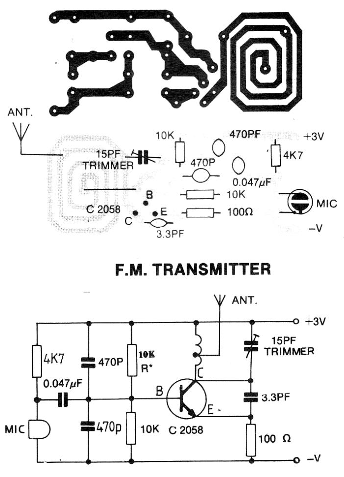
 This tutorial is for making simplest FM transmitter using only one transistor. VC1 is a small, screw-adjustable, trimmer capacitor and its rating should be around 10-100pF. Set your FM receiver for a clear, blank station. Then, with a non-conductive tool, adjust the capacitor for the clearest reception, rotate it till the receiver receives a sound from the microphone of transmitter. Use the following formula for determining the frequency.
Posted on Monday, February 25, 2013 • Category: FM Transmitters
 For months I’ve been looking for a simple FM BUG project, the ones online require inductors which you either have to acquire or build, if you don’t have a LCR meter it becomes rather hard to get the circuit working, specially if you’re a beginner without an oscilloscope! – Sometimes they don’t even tell you which inductance is required and you have to calculate an estimate, which is the main reason why many high frequency RF projects fail in the first place. This circuit on the other hand performs pretty well, even if you’re manipulating the board or touching the coax it will stay within the tuned frequency (unless you touch the transistor or timing capacitor!).
Posted on Saturday, February 16, 2013 • Category: FM Transmitters
 The objective of this 3V FM Transmitter design is to provide a simple low-power transmitter solution for broadcasting audio from various audio sources. This transmitter transmits audio using small sensitive microphone. Transmitter's frequency, as built is tunable via 15pF trimmer to the desired frequency, and the coil is embedded on the circuit board. This implementation is adapted to rebroadcast the output of a CD player, television receiver, or radio receiver. I use this transmitter so that I can move about the house and listen to my favorite programs without disturbing others. Within and the house, I find that I can get 50 to 100 meters away from the transmitter with the small pocket FM receiver I carry in my shirt pocket.
Posted on Sunday, February 10, 2013 • Category: FM Transmitters
 This little broadcast FM transmitter has 500mW of RF output power and runs of 12-15V battery or power supply. DC whose signal modulated by FM using four transistors. Transmitter includes four transmitter stages and draws around 100-150mA of current. Using the values of the circuit components, the frequency will be around 100 MHz but can be changed via coil. Through the 5 pF capacitor and 10K ohm resistor, the modulation of audio signal is supplied to the tank circuit. The amount of modulation is being managed by the 1N4002, a general purpose rectifier diode. FM Transmitter's output stage is functioning as a class D amplifier where the output transistors act as a switch.
Posted on Wednesday, January 16, 2013 • Category: FM Transmitters
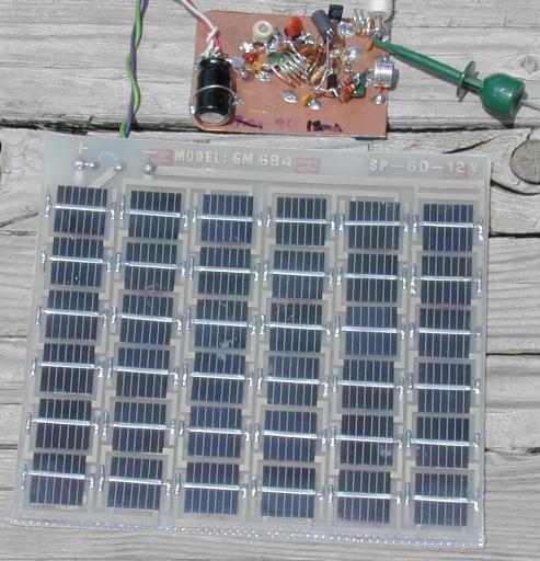 There are many miniature FM transmitter bug circuits online, this one is unique in that it runs completely on solar power. No battery is required. As long as the sun is shining on the PV panel, the transmitter will transmit. The transmitter bug is useful as a "remote ear", and can be used for anything from listening birds to surveillance work. The mic preamp and oscillator circuits were borrowed from a common circuit found around the Internet, a regulated solar power supply and an RF amp that extends the range of transmitter and improves frequency stability were added.
Posted on Sunday, December 23, 2012 • Category: FM Transmitters
 Build your own simple mini FM transmitter. This fun project will show you how to build a mini broadcasting transmitter that can transmit an audio signal up to a quarter mile to any FM receiver. It's easy to build and a good learning experience. It serves as a hands-on learning tool for students or anybody interested in electronics. Having a range of up to a quarter mile, it's great for a house security system, baby monitoring device or simply a listening gadget that you can place anywhere!
Posted on Tuesday, December 4, 2012 • Category: FM Transmitters
 The power output of many transmitter circuits are very low because no power amplifier stages are incorporated. The transmitter circuit described here has an extra RF power amplifier stage using 2N3866 RF power transistor after the oscillator stage to increase output power to 250 milliwatts. With a good matching 50-ohm ground plane antenna or multi-element Yagi antenna, this transmitter can provide reasonably good signal strength up to a distance of about 2 kilometers. Transmitter's oscillator is built around BF494 transistor T1. It is a basic low-power variable-frequency VHF oscillator. A varicap diode circuit is included to tune the frequency of the transmitter and to provide frequency modulation by audio signals. The output of the oscillator is about 50 milliwatts. 2N3866 transistor T2 forms a VHF-class A power amplifier. It boosts the oscillator signal power four to five times. Thus 250mW of power is generated at the collector of transistor T2.
Posted on Sunday, November 18, 2012 • Category: FM Transmitters
 Presented FM transmitter bug is built using BF414 / BF324 / BF606 transistor. The 30cm antenna has a range of about 30m in the building, more in the open field. Power supply 2x AAA batteries have been used with voltage of 2.75 V. I added resistor 10K in parallel with 1.5pF capacitor so that the system works well when connected to an external source (mp3 player / computer). On the computer I had to reduce sound to about 35% of capacity, so that I do not have clipping. I managed to improve transmitter stability with simple shielding. The coil is 5 turns of enameled copper wire wound on 1 mm ø = 5 mm.
Posted on Friday, October 26, 2012 • Category: FM Transmitters
 BA1404 transmitter includes onboard RF amplifier for increased transmitting range. Operating voltage range is 1-3V, the circuit contains FM stereo mixer, 38KHZ oscillator, FM modulator and high-frequency amplifier monolithic integrated circuit. As the "electronic newspaper" BBS there are many users requiring detailed information on the FM stereo transmitter, so I re-collect the relevant information on the simple discrete, merge, integrated FM stereo transmitter experiment, that BA1404 with μpc1651 mix of the most easy to make and debug, and very high frequency stability (relative to the previous circuit BA1404), transmission power is increased by UPC1651RF amplifier.
Posted on Sunday, October 7, 2012 • Category: FM Transmitters
 A high quality stereo FM transmitter circuit is shown here. The circuit is based on the IC BA1404 from ROHM Semiconductors. BA1404 is a monolithic FM stereo modulator that has built in stereo modulator, FM modulator, RF amplifier circuitry. BA1404 FM transmitter can be operated from 76 to 108MHz and power supply for the circuit can be anything between 1.25 to 3 volts.
Posted on Sunday, September 16, 2012 • Category: FM Transmitters
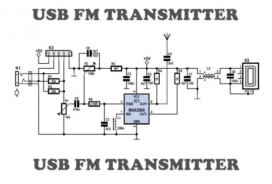 Here is a simple USB FM transmitter that could be used to play audio files from an MP3 player or computer on a standard VHF FM radio by connecting it to an USB port. The circuit use no coils that have to be wound. This USB transmitter can be used to listen to your own music throughout your home. To keep the fm transmitter circuit simple as well as compact, it was decided to use a chip made by Maxim Integrated Products, the MAX2606. This IC from the MAX2605-MAX2609 series has been specifically designed for low-noise RF applications with a fixed frequency. The VCO (Voltage Controlled Oscillator) in this IC uses a Colpitts oscillator circuit. The variable-capacitance (varicap) diode and feedback capacitors for the tuning have also been integrated on this chip, so that you only need an external inductor to fix the central oscillator frequency.
Posted on Monday, August 20, 2012 • Category: FM Transmitters
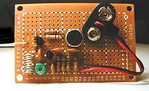
 This easy to build FM transmitter bug can transmit voice to exceptionally good range. Tune trimmer to hear the signal to your near radio. Transmitter frequency range is 88-108 MHz. Max current consumption is 30mA. You can power the fm transmitter bug with a 9Volt Battery, or you can plug a power supply to feed in 9-12 Volts. That bug will pick even a low whisper or even the sound of a breath well far from the microphone. Great spy transmitter equipment.
Posted on Saturday, June 23, 2012 • Category: FM Transmitters
 After building FM transmitter I decided to build a 6W RF Transmitter amplifier for the FM band to get more power and we chose to copy a 6 Watt design built around 2SC1971 RF power transistor. We were not satisfied with finished result and decided to replace the fixed capacitors around the pcb inductors with variable capacitors, this is much better and possible to tune to your transmitter frequency.
Posted on Friday, June 8, 2012 • Category: FM Transmitters
 The 1 watt 20 meter QRP transmitter with VXO. This is a nice QRP transmitter that can be used in combination of one of the simple receivers.
Normally these designs have only two transistors: one is the X-tal oscillator and the second the final amplifier. A good example is my first QRP rig that is also described somewhere on this site. Here the VXO (Variabele X-tal Oscillator) has a tuning range of 16 kHz. This VXO is buffered with an extra driver stage for a better frequency stability and a varicap diode is used instead of a variabele capacitor. An extra transistor is added for keying the transmitter with a low keying current.
What you can do with such a simple 1 watt QRP power transmitter.
This is a real low power transmitter, so do not expect that you can do everything with it but...
When conditions are normal, you can easily make many QSO's during one afternoon with stations with distances upto 2000 km with a simple inverted V wire dipole antenna! From Europe, I did even make QSO's across the Ocean!
Posted on Tuesday, May 29, 2012 • Category: FM Transmitters
 This PLL transmitter is controlled and the frequency is very stable and can be programmed digitally. Transmitter will work 88-108 MHz and output power up to 500mW. With a small change can set the frequency of 50-150 MHz. The output power is often set to several watts with transistors. So therefore I decided to build a simple transmitter with great performances. The frequency of this transmitter can easily be changed by software and space / compress air coil. This transmitter is the oscillator colpitts. Oscillator is a VCO (voltage controlled oscillator) which is set by the PLL circuit and PIC micro controller. This oscillator is called the Colpitts oscillator and voltage controlled to achieve the FM (frequency modulation) and PLL control.
Posted on Wednesday, May 2, 2012 • Category: FM Transmitters
 This is the schematic for an FM transmitter with 3 to 3.5 W output power that can be used between 90 and 110 MHz. Stability of this transmitter is not bad and PLL circuit can be added on.
This is a circuit that I've build a few years ago for a friend, who used it in combination with the BLY88 amplifier to obtain 20 W output power. From the notes that I made at the original schematic, it worked fine with a SWR of 1 : 1.05 (quite normal at my place with my antenna).
Posted on Sunday, April 1, 2012 • Category: FM Transmitters
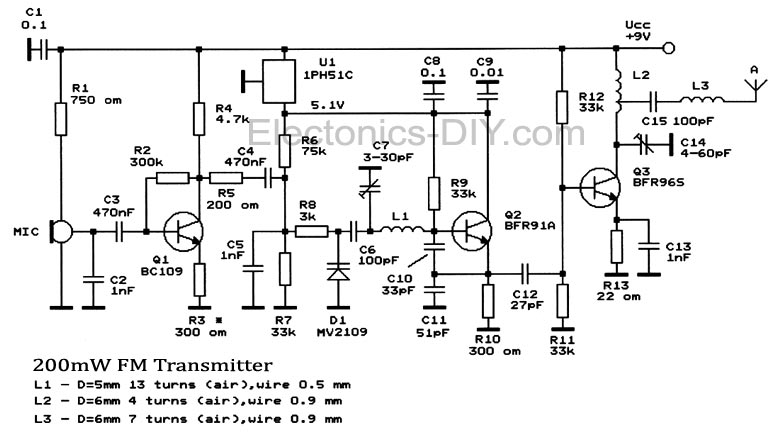 A simple 200mW FM Transmitter circuit which covers frequencies from 88 to 108 MHz. It is built with 3 transistors: BC109, BFR91A and BFR96S. It is quite stable and the output power is around 200mW.
The first stage of transmitter is a mic amplifier but if you connect this radio transmitter directly to an audio source you can remove this stage and connect the audio signal to R5.
U1, 1PH51C can be replaced with LM7805. You must use a stabilized power source for oscillator stage to prevent frequency variation. You can remove C7 and use a linear potentiometer instead of R6 with the median connector to C4, one pin to ground and the other one to +. FM Transmitter uses MV2109 varicap diode and C7 for frequency tuning.
Posted on Tuesday, March 20, 2012 • Category: FM Transmitters
 The RF oscillator using the inverter N2 and 10.7Mhz ceramic filter is driving the parallel combination of N4 to N6 through N3.Since these inverters are in parallel the output impedance will be low so that it can directly drive an aerial of 1/4th wavelength. Since the output of N4-N6 is square wave there will be a lot of harmonics in it. The 9th harmonics of 10.7Mhz (96.3Mhz) will hence be at the center of the FM band. N1 is working as an audio amplifier. The audio signals from the microphone are amplified and fed to the varicap diode. The signal varies the capacitance of the varicap and hence varies the oscillator frequency which produce Frequency Modulation.
Posted on Wednesday, February 15, 2012 • Category: FM Transmitters
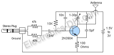
 With this circuit you can build a very small tracking transmitter that can be tracked using a FM broadcast band radio receiver. The transmitter can be powered from any 1.5V volt battery or power supply. Transmitter has a range up to 1 mile depending on battery voltage, height above ground, receiver sensitivity, and antenna length. Under certain conditions distances of 1 mile have been achieved. It is recommended that this transmitter be used with FM radios that can tune continuously across the dial. The better the receiver and receiver antenna system the greater the practical range of the transmitter, however good functionality can be achieved with the least expensive radios and using only the standard telescoping antenna included with most radios.
Posted on Tuesday, February 7, 2012 • Category: FM Transmitters
 Here's BH1417 USB FM Transmitter with built-in PLL circuit. Its low-frequency signal is converted into high-frequency, which can take any audio device with FM radio (stereo, car CD, MP3, DVD player, etc.), as a normal radio station. Transmitter power is sufficient for reliable reception of its signal within a few tens of meters. The basis of the device is a chip BH1417F, included in a typical scheme. This device contains all the necessary circuitry to generate a composite stereo signal c of the pilot tone, the RF generator with PLL and power amplifier. A detailed description is given in.
Posted on Wednesday, February 1, 2012 • Category: FM Transmitters
 Here's a long range 300mW FM Transmitter for the 88MHz to 108MHz band. This particular TX is of special interest to those wishing to build low power Power Amplifiers for the VHF bands since it used impedance matching, power amplifier and antenna filtering, all of which should be used by radio constructors, whether it be for amateur radio or any other form of radio. The features of this project are: Higher output power - 150mW min (at 9v) and 300mW+ (at 12.5v). Very pure output signal due to careful design and filtering. VARICAP modulation - possibility to add a synthesizer. Single sided Printed Circuit Board, only 40mm x 72mm. Covers the domestic FM band - 88MHz to 108MHz. Easy to build, but coil winding experience IS required
Posted on Tuesday, January 17, 2012 • Category: FM Transmitters
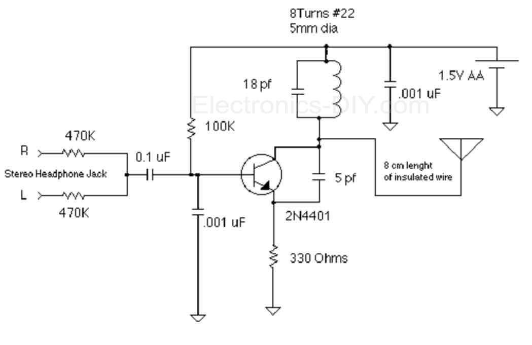 The objective of this 1.5V FM Broadcast Transmitter design is to provide a simple low-power transmitter solution for broadcasting audio from various audio sources. This transmitter accepts stereo input via two 470K resistors. Since there is no audio level control on the input, the audio level out from the source needs to be adjusted. Or, you can just add a 10k as an input level control. Transmitter's frequency, as built is tunable via spreading or compressing the coil to the desired frequency, and the coil can be glued down. If you want to make one that's tunable, it might be easiest to reduce the 18 pf capacitor and put a small trimmer capacitor in parallel with the inductor (across the reduced value capacitor). Voltage variable capacitors would be an nice alternative to a mechanical variable capacitor but they don't offer much tuning range with only a 1.5V power supply.
Posted on Sunday, January 8, 2012 • Category: FM Transmitters
 This FM Broadcast Transmitter circuit will transmit a continuous audio tone on the FM broadcast band (88-108 MHz) which could used for remote control or security purposes. Circuit draws about 30 mA from a 6-9 volt battery and can be received to about 100 yards. A 555 timer is used to produce the tone (about 600 Hz) which frequency modulates a Hartley oscillator. A second JFET transistor buffer stage is used to isolate the oscillator from the antenna so that the antenna position and length has less effect on the frequency. Fine frequency adjustment can be made by adjusting the 200 ohm resistor in series with the battery. Oscillator frequency is set by a 5 turn tapped inductor and 13 pF capacitor.
Posted on Friday, December 30, 2011 • Category: FM Transmitters
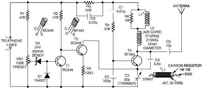 Here is a very simple telephone broadcaster transmitter which can be used to eavesdrop on a telephone conversation. The circuit can also be used as a wireless telephone amplifier.
One important feature of this phone transmitter is that the circuit derives its power directly from the active telephone lines, and thus avoids use of any external battery or other power supplies.
Posted on Wednesday, December 28, 2011 • Category: FM Transmitters
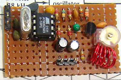
 In this project, you will make a simple 3-stage low-power broadcast-type circuit, using a crystal oscillator integrated circuit and an a collector modulated AM oscillator with amplifier. You can connect the circuit to the an electred microphone or amplified dynamic microphone. Using an electred microphone is shown (in gray) in the diagram below. (no amplified dynamic microphone has a to low output voltage to work. at least 100mv is needed). You could also add a LF preamp stage of one transistor to allow connecting a dynamic microphone directly.
You'll see that you can receive the signal through the air with almost any AM radio receiver. Although the circuits used in radio stations for AM receiving are far more complicated, this nevertheless gives a basic idea of the concept behind a principle transmitter. Plus it is a lot of fun when you actually have it working!
Remember that transmitting on the 10 meter band you'll need a valid radioamateur license!!
A wide range of different circuits have been used for AM, but one of the simplest circuits uses collector modulation applied via (for example) a transformer, while it is perfectly possible to create good designs using solid-state electronics as I applied here (T1 BC557).
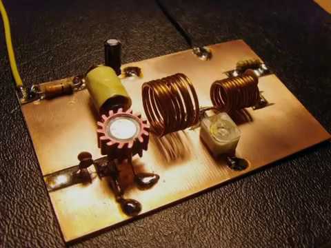
The transmitter is build as a Colpitts Oscillator with a BSX20 transistor. HF-output of the oscillator is approx. 50 mW, depending on the supply voltage of 6 to 15 Volts. This is amplified by the BD135 and brings the power up to approx. 1 watt @ 12volts. The transmit frequency is stabilized with the 28Mhz crystal. A slight detuning of approx 1kc is possible when using a 120pF trimmer capacitor for C8. The oscillator signal is taken from the collector of T2 and guided to the input of T3 which output is lead via an L-filter and low-pass PII filter circuit cleaning up the signal pretty good and ensuring spectral purity. The oscillator is keyed by T1 and the morse key (S). By keying the morse-key T1 is not been used for modulation and is biased, hence lets T2 freely oscillate.
Posted on Thursday, December 15, 2011 • Category: FM Transmitters
 This small FM transmitter with a range of about 50 meters designed for hoby. With lots of mini-transmitters then you have a comprehensive, action-packed radio program. Due to the power supply via the USB port of a high frequency stability is achieved. Alternatively, the receiver, a battery 5 to 12 volts to operate.
Posted on Tuesday, December 6, 2011 • Category: FM Transmitters
 Here are instructions for building your own ipod FM radio transmitter. It works quite easy, there is a power switch on the bottom to turn it on and tune your radio and transmitter to the right frequency. For the antenna you can use a copper wire of 70 cm. The range of this FM transmitter is about 100 to 150 meters (500 feet). With R5 you can adjust the input signal and with C6 you can tune your frequency. Transmitter is supplied by 9V battery.
Posted on Friday, December 2, 2011 • Category: FM Transmitters
 With this Stereo FM Transmitter with BA1404 you will be able to create a mini stereo FM station and broadcast to your entire home, a simple way to have an audio link wireless with ease. With the FM transmitter BA1404 Hifi Stereo you can stream your music from your iPod MP3, satellite receiver, computer, DVD player, Mobile Phone, MP4 player and MP3 and other audio source directly to an FM receiver with crystal clear sound.
Posted on Friday, November 18, 2011 • Category: FM Transmitters
 Here's simple FM transmitter circuit using medium power 2N2218 transistor. Micropohone is of electret type that connects to two input terminals and the antenna should be a copper wire from 15 to 40 cm. Below is schematic circuit of the fm transmitter.
Posted on Friday, October 28, 2011 • Category: FM Transmitters
 Here's 1W RF Amplifier is for boosting small fm transmitters and bugs. It use two Philips 2N4427 and its power is about 1Watt. At the output you can drive any linear with BGY133 or BLY87 and so on. Its power supply has to give 500mA current at 12 Volts. More voltage can boost the distance but the transistors will be burned much earlier than usual.! In any case do not exceed the 15Volts. The Amp offers 15 dB in the area of 80Mhz to 110 Mhz. L4, L5, and L6 are 5mm diameter air coils, 8 turns, with wire 1mm wire diameter.An easy project, with great results.
Posted on Sunday, October 23, 2011 • Category: FM Transmitters
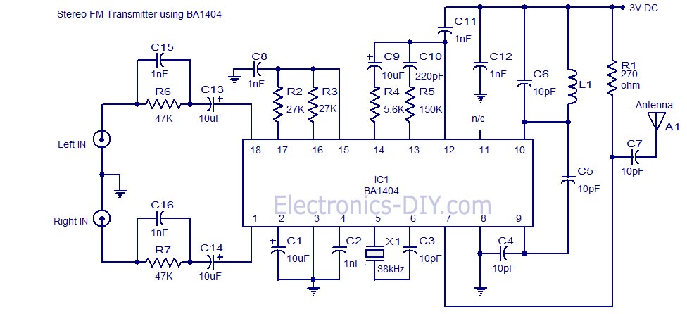 A high quality stereo FM transmitter circuit is shown here. The circuit is based on the IC BA1404 from ROHM Semiconductors. BA1404 is a monolithic FM stereo modulator that has built in stereo modulator, FM modulator and RF amplifier. The FM modulator can be operated from 76 to 108MHz and power supply for the circuit can be anything between 1.25 to 3 volts.
In the circuit R7, C16, C14 and R6, C15, C13 forms the pre-emphasis network for the right and left channels respectively. This is done for matching the frequency response of the FM transmitter with the FM receiver. Inductor L1 and capacitor C5 is used to set the oscillator frequency. Network C9,C10, R4,R5 improves the channel separation. 38kHz crystal X1 is connected between pins 5 and 6 of the IC. Composite stereo signal is created by the stereo modulator circuit using the 38kHz quartz controlled frequency.
Posted on Tuesday, October 18, 2011 • Category: FM Transmitters
 This simple FM Transmitter takes audio input through a 1/4" phono jack and, constructed as shown, without the optional antenna connections, will broadcast an FM radio signal about 30 feet. This is the standard model of simplest FM transmitters includes a trim capacitor to adjust the transmitting frequency. It can be powered by a 9V battery and uses a hand-turned copper coil. The circuit is extraordinarily simple and could be built on perfboard or on a panel almost as easily.
Posted on Wednesday, October 12, 2011 • Category: FM Transmitters
 This is a simple design of a small FM Transmitter Bug that's perfect for transmitting and eavesdropping purposes. Due to the high sensitivity, even the ticking of the clock to hear. The range is estimated at anything from 50 meters. With a small piece of wire as an antenna to get at least the whole house. L1 and L2 are two equal air pools. They each consist of 5 turns at a diameter of about 4 mm. The thickness of the wire does not matter, 0.5 mm works perfectly. C4 is the frequency adjustment. Tune an FM radio in an empty area of the FM band and C4 to turn your silence or hear a whistle. From what you can precisely adjust the radio and the transmitter installed in a room somewhere to intercept. Note: Because these transmitter bugs inherently unstable, you better read the short legs of the components keep the circuit mechanically tightly together up. Also placing a 1 nF capacitor (C6) will benefit stability.
R1, R3, R4: 4K7
R2: 100K
R5: 10K
R6: 270 Ohms
C1, C2: 10 uF
C3, C6: 1 nF
C4: 2-18 pF trimmer
C5: 5.6 pF
L1, L2: air puddle windings on May 4 mm in diameter (see text)
T1, T2: 547 BC
Condenser microphone
Original Text:
Ook het plaatsen van een 1 nF condensatortje (C6) over de voedingsaanluitingen komt de werking ten goede. [Origineel TinyCAD ontwerp]
Show alternative translations
Posted on Friday, September 23, 2011 • Category: FM Transmitters
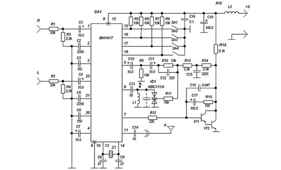
 The circuit shown here is of a good Stereo FM transmitter that can transmit high quality signals up to a range of 70 feet. The circuit is based on BH1417 PLL stereo transmitter IC from Rhom semiconductors. The IC has separate audio processing sections for the left and right channels, pre emphasis circuit for improving signal to noise ratio, crystal control circuitry for accurate frequency locking, multiplex circuit for making sum ( left plus right) and difference ( left minus right) {see this article for better understanding Stereo decoder circuit} etc. Another important feature of this IC is that the transmission frequency can be set using a 4 channel DIP switch. The IC can be powered from anything between 4 to 6V DC and has an output power around 20mW. At full output power the circuit consumes only 20mA and has a channel separation of 40dB.There are 14 possible preset transmission frequencies, starting from 88.7MHz and incrementing in steps of 0.2MHz that can be selected using the DIP switch. The PLL circuitry of the IC is so precise that there is practically no frequency drift.
Posted on Thursday, August 25, 2011 • Category: FM Transmitters
 This miniature transmitter is easy to construct and it's transmissions can be picked up on any standard FM receiver. It has a range of up to 1/4 of a mile or more. It is great for room monitoring, baby listening, nature research, etc. L1 is 8 to 10 turns of 22 gauge hookup wire close wound around a non-conductive 1/4 inch diameter form, such as a pencil. C4 is a small, screw-adjustable, trimmer capacitor. Set your FM receiver for a clear, blank space in the lower end of the band. Then, with a non-conductive tool, adjust this capacitor for the clearest reception. A little experimenting and patience may be in order. Most of the parts' values are not critical, so you can try adjusting them to see what happens.
Posted on Monday, August 8, 2011 • Category: FM Transmitters
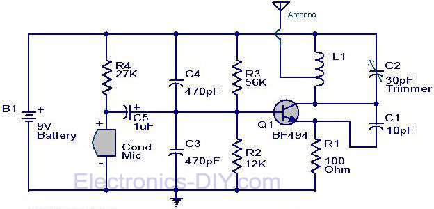 Here is the circuit diagram of the simple FM transmitter using a transistor. Great performance or range is not guaranteed here, because this is an elementary design. General purpose radio frequency transistor BF 494 (Q1) is used here for obtaining FM modulation. A condenser mic is used here to pickup the sound.The condenser mic converts the sound to electrical variations and this variations are fed to the base of Q1 , which performs the amplification as well as modulation.The capacitor C2 and L1 determines the frequency of transmission.The circuit can be powered from a 9V transistor radio battery.
Posted on Thursday, August 4, 2011 • Category: FM Transmitters
 FM transmitter or often called fm transmitter uses 2 transistors in this article uses 2 transistors 2n2222. If the fm transmitter is in use voltage supply of 9 volt battery and use an antenna whose length is less than 12 inches, then this fm transmitter will be within FCC limits.
Signals from the microphone in the fm transmitter is reinforced by Q1, Q2 with carrier frequency generator is determined by the C5 and L1. The frequency of the FM transmitter is in the range 80 MHz - 108 MHz. L1 can be made with as many as 24 e-mail wire wrap and 6 wrap. The following is a picture series for the fm transmitter fm transmitter referred to in article 2 of this transistor.
Posted on Monday, August 1, 2011 • Category: FM Transmitters
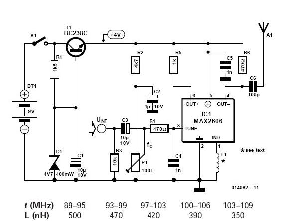 If you want to be independent of the local radio stations for testing VHF receivers, you need a frequency-modulated oscillator that covers the range of 89.5 to 108 MHz — but building such an oscillator using discrete components is not that easy. Maxim now has available a series of five integrated oscillator building blocks in the MAX260x series which cover the frequency range between 45 and 650 MHz. The only other thing you need is a suitable external coil, dimensioned for the midrange frequency.
Posted on Wednesday, July 27, 2011 • Category: FM Transmitters
 A very good 1 watt fm transmitter circuit, very easy to build circuit. It has 4 transistors, one is a very stable oscillator, followed by a buffer stage to prevent frequency variation when you adjust the transmitter. Next is a resonance stage and the final stage built with a minimum 1W transistor which must have a heatsink. You must use a LM7805 stabilizer for the oscillator diodes and one LM7809 for powering up the T1 oscillator stage. This will give you a very stable transmitter frequency.
Posted on Monday, July 18, 2011 • Category: FM Transmitters
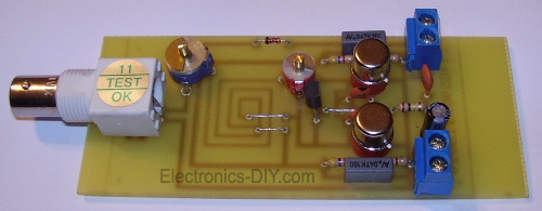 This 2 Watt FM transmitter will provide 10km range in good weather conditions. Use dipole antenna for maximum range. Transmitter can be tuned between 88-108 MHz with c5. BB204 could be replaced with conventional led (big) with reverse bias (no light given in correct polarity). 9v power for 2km transmission with good sound quality and up to 18v for 10km range. 2N3553 RF transistors may be replaced with 2N4427 or 2N3866.
Posted on Friday, July 15, 2011 • Category: FM Transmitters
 This RF Amplifier designed for FM broadcast using a single 2SC1946 VHF Power Transistor. This 10-30W RF amplifier circuit provides an appropriate power boost with an input of 1-3 watt. Tower are 30 meters high will send signal surrounding air should be around 15 km. The layout of the 2SC1946 28 Watts FM broadcast RF amplifier has been created with Eagle. The pcb outline is 100 x 50 mm (width x height), all bitmaps have a resolution of 600dpi.Use FR-4 single sided photoresist epoxy pcb material for best results.
Posted on Thursday, July 14, 2011 • Category: FM Transmitters
 This is a very simple 5 watt CW TX based upon a TTL logic chip. There is just one "tricky" component and this is Cx. This component should have an impedance of about 10 - 50 ohms at the frequency of interest. If you wish to reduce the transmitter power, increase the value of Cx. It is Cx which causes the square wave from the output transistor to approximate a sine waveform. The value of Cx is the price of simplicity in this TX.
Posted on Monday, July 11, 2011 • Category: FM Transmitters
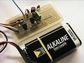 This Wireless Microphone FM Transmitter has been a very popular project with beginners and experienced constructors alike. It has been used inside guitars and as the basis of a remote control system. I do however, receive many requests for a higher powered circuit and better microphone sensitivity. Now I can introduce the new FM Wireless Microphone, which also has a better frequency stability, over 1Km range (under ideal conditions) and is good on microphone sensitivity. This has been achieved by adding an RF amplifier buffer (with 10dB gain) and an AF preamplifier to boost the modulation a little.
Posted on Friday, July 8, 2011 • Category: FM Transmitters
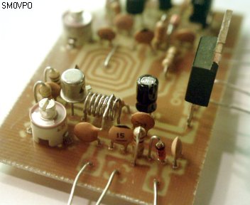 The transmitters on my homepage seem to be quite popular, especially those intended for the 88 - 108MHz FM band. I must really confess that I also favor this broadcast band, mainly because it is so easy to find signals on the workshop radio. Everyone has an FM radio, and it is fun to play with. Experimental antennas and the like can all be developed in this band since there are a huge range of "beacons" all transmitting just for my benefit :-). Basic oscillators also are easy to fault-find in this frequency band, and then later modified for other VHF bands.
The V5 FM Wireless Microphone is a 10mW transmitter that featured a coil fabricated on the PCB itself. This made the project easy to duplicate and removed "microphony" (the ability of coils to act as a microphone with spring-line reverb). But as several people have already commented, although more stable than most other similar kits and projects, the frequency still does vary with battery voltage. In just one session it can vary by 200kHz when a cheap "Mighty Atom" battery falls to 8 volts.
Posted on Thursday, July 7, 2011 • Category: FM Transmitters
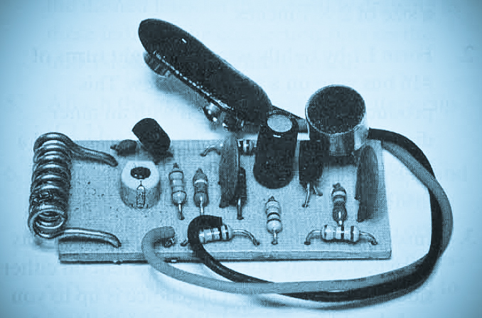 Presented here is a Long Range FM Transmitter. This circuit is a super-sensitive, mini-powered FM transmitter consisting of a RF (radio Frequency) oscillator section interfaced with a high sensitivity, wide pass-band audio amplifier and capacitance mike with a built-in FET (Field Effect Transistor) that modulates the base of the RF oscillator transistor. Transistor Q1 forms a relatively stable RF oscillator whose frequency and is determined by the value of coil L1 and turning capacitor C4.
Posted on Thursday, June 30, 2011 • Category: FM Transmitters
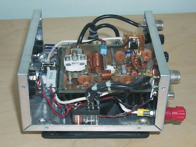 This is a 6m band transmitter RF power amplifier (50 MHz) with 100W output. It used with my FT-736R and drive from 10W for the 6m SSB DX. The Building information comes from Japan CQ Magazine. The Toshiba RF bipolar power transistor is used in it.
If you want to construct this rf amplifier, it's the better way if the double side PCB use for increase the grounding and current transfer. The TX power can be tune to 120W.
Posted on Tuesday, June 28, 2011 • Category: FM Transmitters
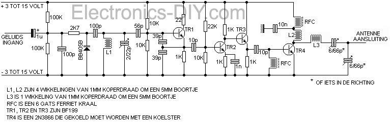 Presented here is a 1.5 Watt FM Transmitter. A transmitter is an installation in which electrical oscillations are generated by an antenna as radio waves are emitted.Although there are a variety of channels exist in terms of size, application and frequency, each transmitter is an oscillator is present (usually crystal controlled) that an electric thrill, the carrier, with a constant frequency electricity.This is followed by one or more selective amplifier stages tuned oscillation circuits, which usually frequency multiplication is performed.Modulation can occur at low power, and even strengthening of the modulated signal to the power required to reach.Modulation can also occur at high power, when the carrier signal and separately reinforced.
Posted on Thursday, June 23, 2011 • Category: FM Transmitters
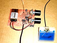 Most transmitter has several variable capacitors which are used to match impedance for transistors and antennas. I know people hate trimmers and so did I. The reason is that it is difficult to trim a system if you can't measure the performances.
To trim a transmitter you need to measure the output power.
Most transmitter are tuned with a dummy load of 50 ohm to substitute an antenna of 50 ohm.
Not everyone has a power meter, and how can you know that the antenna you connect is purely 50 ohm.
If not, the hole trimming is waste of time!
What you would like to do is to measure the radiated power out from the antenna you actually are going to use.
If you can measure the radiated energy field you can easy tune the system for max output field strength (max power).
So, how can we measure the radiated energy field?
The block diagram at right show you one easy way to measure the RF filed strength. To the left you find a dipole antenna.
The antenna should be cut to match the receiving frequency ...
Posted on Wednesday, June 22, 2011 • Category: FM Transmitters
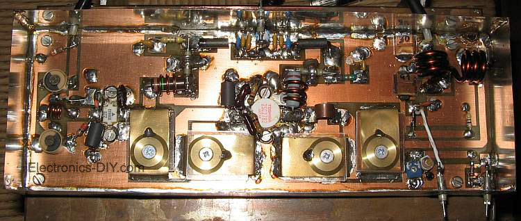 This is 80W RF power amplifier that boosts FM Transmitter's power using 2SC2782 bipolar transistors in a tuned class C circuit. RF amplifier can be driven to full 80W power with less than 1 watt driving input power, so that a large gain margin results in this FM transmitter.
To obtain stability in this RF amplifier, I employed several techniques, such as placing the resonances of base and collector chokes far apart, damping the chokes with resistors, using RC combinations for absorption of unwanted frequencies, using feed trough capacitors for bypassing on the board, etc. It took some tweaking, but the amplifier ended up unconditionally stable.
Posted on Friday, June 17, 2011 • Category: FM Transmitters
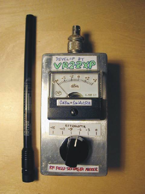 RF Field Strength Meter with Attenuator up to 200 MHz
The RF field meter unit is a great help to tune transmitters for best performance and output power. You can measure the radiated energy field and can easy tune the system for max output field strength maximum power.
This field strength meter comes with selectable attenuator. You can use it for measuring the antenna gain and pattern, compare different magnetic field strengths. See the following RF field strength meter schematic.
Posted on Friday, June 17, 2011 • Category: FM Transmitters
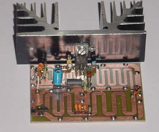 Here's 8W broadband FM RF amplifier using 2SC1971 VHF power transistor. The RF Amplifier PCB layout designed for FM broadband 88-108 MHz transmitters using microstripline technique. This 8W RF amplifier circuit provides an appropriate power boost for transmitters with an input of 500 mW.
Posted on Tuesday, June 14, 2011 • Category: FM Transmitters
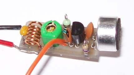 A very small home made FM transmitter Bug using a single transistor and with a transmission range of 200 meters. This FM transmitter Bug is very easy to build. The size of the circuit board is ONLY 22mm x 10mm.
Posted on Saturday, June 11, 2011 • Category: FM Transmitters
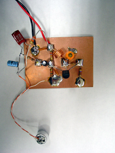 Here's how to build a simple FM Transmitter. This tiny transmitter has smaller radius of the service area, lower quality of the sounds and the relatively unstable frequency. These can be considered as a compromise to easily have your own transmitter for the time being or as a more positive choice. These "defects" are only from the perspective of conventional transmission such as "clear stereo sound to receive anywhere". Artist could change these to another directions. Whether or not, you can experience a convivial wireless imagination by this transmitter.
Posted on Thursday, June 9, 2011 • Category: FM Transmitters
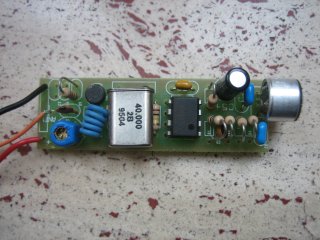 This micro spy PLL FM Transmitter transmits on the 160MHz frequency (if we use a 40MHz quartz) and therefore can be listened through a receiver tuned on this frequency. This circuit can be used to on various frequencies, for example on the FM band 88-108 just modifying some components, among which the quartz (25MHz).
Voice is detected by an electret microphone, then it is amplified and filtered by U1 pass-band in order then to be modulated from the carrier section, where through the varicap diode it "mixes" with the frequency generated by the quartz, that guarantees an adapted stability. Practically the modulating voltage is obtained applying the audio signal to the resonating circuit varicap diode that determines the carrier oscillation. The carrier frequency (160 MHz) must be greater than the modulating frequency (300-3300 Hz) audio band.
The transmission is on the fourth harmonic, therefore 160MHz, the oscillation frequency of the driver RF transistor Q1.
A small calibration is allowed acting on the L1 inductance and the C1 Trimmer Capacitor.
Posted on Wednesday, June 8, 2011 • Category: FM Transmitters
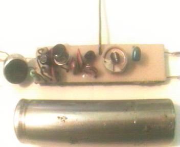 Mini FM transmitters take place as one of the standard circuit types in an amateur electronics fan's beginning steps. When done right, they provide very clear wireless sound transmission through an ordinary FM radio over a remarkable distance. I've seen lots of designs through the years, some of them were so simple, some of them were powerful, some of them were hard to build etc.
Here is the last step of this evolution, the most stable, smallest, problem-less, and energy saving champion of this race. Circuit given below will serve as a durable and versatile FM transmitter till you break or crush it's PCB. Frequency is determined by a parallel L-C resonance circuit and shifts very slow as battery drains out.
Posted on Friday, May 27, 2011 • Category: FM Transmitters
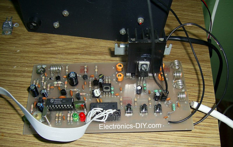 This is 8W PLL Stereo Transmitter with LCD. It is a stable PLL FM transmitter based on TSA5511 synthesizer. Frequency is performed with three buttons through PIC16F84 microcontroller. Frequency of the transmitter is displayed on 16x1 LCD. Transmitter oscillator is based around BF981, BFR91, BFR96 transistors. 2SC1971 RF power transistor can be replaced with 2N4427 or 2N3553 but they will provide less output power.
Posted on Friday, May 20, 2011 • Category: FM Transmitters
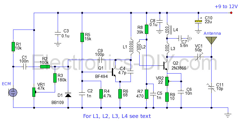 The power output of many transmitter circuits are very low because no power amplifier stages are incorporated. The transmitter circuit described here has an extra RF power amplifier stage, after the oscillator stage, to raise the power output to 200-250 milliwatts. With a good matching 50-ohm ground plane antenna or multi-element Yagi antenna, this transmitter can provide reasonably good signal strength up to a distance of about 2 kilometres. The circuit built around transistor T1 (BF494) is a basic low-power variable-frequency VHF oscillator. A varicap diode circuit is included to change the frequency of the transmitter and to provide frequency modulation by audio signals. The output of the oscillator is about 50 milliwatts. Transistor T2 (2N3866) forms a VHF-class A power amplifier. It boosts the oscillator signal power four to five times. Thus, 200-250 milliwatts of power is generated at the collector of transistor T2.
Posted on Monday, May 9, 2011 • Category: FM Transmitters
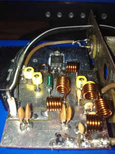 This fm rf amplifier uses 2SC1971 transistor to provide 5 watts of output. Output matching is adjusted via the two 40pF trimmer capacitors likewise also to the input. Note that the emitter of this transistor is directly grounded on the heat sink and should have a good thermal transfer. Driving power of 100 to 200mW can be applied in order to provide 5watts of output. Use a dummy load to tune this amplifier and remember that the transistor is biased in Class C, sufficient filtering should be followed after the output to minimize all the harmonics. Use ground plane construction technique in the PCB lay-out for best result, the more the grounding the better. If you have hard time finding the 10uH rf choke, try to wind 1/2 meter of 0.2mm enamel wire over a 33K 1/2 watt resistor and solder the coil ends to the legs of the resistor.
Posted on Monday, May 9, 2011 • Category: FM Transmitters
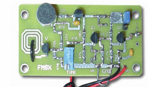 Presented here is a low-power FM transmitter with varactor diode tuning using surface-mount devices (SMD) that will be received with a standard FM radio. Soldering surface mounted devices is not so hard and actually is quite easy. There are many designs for small FM transmitters but they have some problems. First, you need an audio amplifier to get enough modulation. Second, the antenna is attached directly to the collector. Third, the coil L must be wound by hand and adjusted by stretching. It all ads with a weak signal that tends to drift in frequency. In contrast the transmitter schematic we present here eliminates some of those problems, using varactor diode for tuning and modulation, givin great sensitivity without an audio amplifier.
Posted on Sunday, May 8, 2011 • Category: FM Transmitters
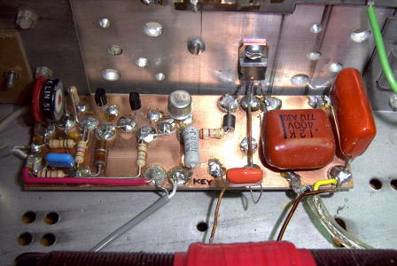 This particular transmitter was later shipped up to VY1JA in the Yukon where, thanks to Jay's excellent antenna system, it was heard in Europe as well as in New Zealand during one of the Trans-Pacific Tests! Running 24 volts on the final will produce 100 watts into a 50 ohm load.
The transmitter utilizes a 4060 binary counter IC chip as both the crystal oscillator and frequency divider. I used a 2200 kHz crystal along with the 'divide-by' sixteen output to produce a signal at 137.5 kHz. Other combinations of crystal frequencies and 'divide-by' combinations may also be used since the 4060 features divided outputs for f/32 (pin 5) and f/64 (pin 4), among others. You may have a 4MHz crystal or an 8MHz crystal in your junk box that will put you in the band using these output pins.
Posted on Thursday, April 28, 2011 • Category: FM Transmitters
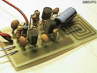 This FM Wireless Microphone has been a very popular project with beginners and experienced constructors alike. It has been used inside guitars and as the basis of a remote control system. I do however, receive many requests for a higher powered circuit and better microphone sensitivity.
This High Power FM Wireless Microphone has a better frequency stability, over 1 Km range and is good on microphone sensitivity. This has been achieved by adding an RF amplifier buffer (with 10dB gain) and an AF preamplifier to boost the modulation a little.
Posted on Thursday, April 28, 2011 • Category: FM Transmitters
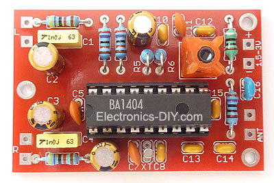 This FM transmitter design is a result of many hours of testing and tweaking. The goal was simple; to test many existing BA1404 transmitter designs, compare their performance, identify weaknesses and come up with a new BA1404 transmitter design that improves sound quality, has very good frequency stability, maximizes transmitter's range, and is fairly simple for everyone to build. We are happy to announce that this goal and expectations have been met and even exceeded.
The transmitter can work from a single 1.5V cell battery and provide excellent crystal clear stereo sound. It can also be supplied from two 1.5V battery cells to provide the maximum range.
One of the qualities of BA1404 FM transmitter is excellent frequency stability. This is mainly due to a use of high quality 3.5 turn variable coil. Tunable RF coils are ideal for precise frequency tuning because their magnet wire is halfway embedded within the plastic, which minimizes frequency drifts. Regular air coils are not preferred for professional broadcasting because the coil expands and contracts with temperature changes. That's the very reason why variable coil was chosen as a substitution for an air coil and a variable capacitor.
Posted on Sunday, April 17, 2011 • Category: FM Transmitters
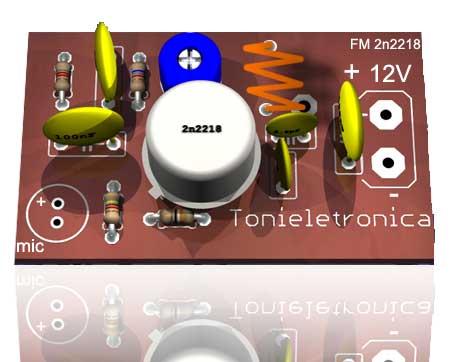 This small power FM transmitter can transmit more than 1 km in good conditions. The modulation can be made so much with a microphone or audio source. Circuit of power fm transmitter is built around 2n2218 transistor. Transmitter coil is 5 turns of enameled 22 AWG wire, with diameter of 1 cm without nucleus. Look at the capacitors that it should be ceramic. The antenna should possess from 15 to 40 cm. For transmission it ties a receiver of FM (radio) in the proximity to half volume in a free frequency (that there is not any radio operating), with a wood or plastic key, rotate the screw of CV to capture the frequency of the transmitter.
Posted on Friday, April 15, 2011 • Category: FM Transmitters
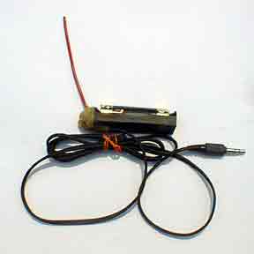 This implementation is adapted to rebroadcast the output of a CD player, television receiver, or radio receiver. I use it so that I can move about the house and listen to my favorite programs without disturbing others. Within and the house, I find that I can get 10 to 20 meters away from the transmitter with the small pocket FM receiver I carry in my shirt pocket. Your mileage may vary. The transmitter as built and pictured below (the transmitter is in the blob of hot melt glue on the end of the battery holder) does not have an on-off switch. I put a 1.5 AA cell that was run down too far to run my CD player in this transmitter and it ran for over a month before I replaced it. The one in the transmitter at this moment has been running it continuously for over three months. Current draw is only about a milliamp with a new battery (assuming you don't have a super-high beta transistor in which case the theoretical limit is about 2.5 ma). An on-off swich is not necessary, though it may satisfy an emotional need.
Posted on Thursday, April 14, 2011 • Category: FM Transmitters
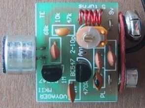 9 Volt battery operated simple Mini FM Transmitter. FM Transmitter is very simple, compact, and has transmission signal with a range of 100-150m, good sensitivity and low current consumption. Transmitter's schematic consists of a bass amplifier for the first transistor and the proper frequency generator in the second. FM Transmitter divided transitional capacitor that allows you to set up a cascade separately.
Posted on Tuesday, April 12, 2011 • Category: FM Transmitters
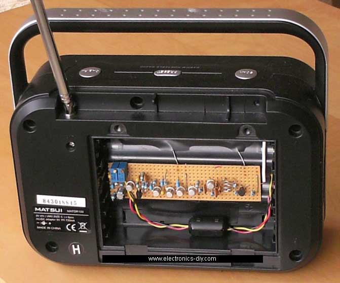 Here's a nice AC mains powered FM Broadcast Audio Transmitter with pre-emphasis, audio level control, and tuning control. The circuit consists of a frequency modulated oscillator, an audio preamplifier with pre emphasis to supply the frequency modulating signal, and a buffer amplifier to drive the antenna connector.
Oscillator's frequency is determined by L1 resonating with the 10 pf capacitor and the total capacitance across it. The collector-base capacitance of the transistors Q3, Q4, and Q5 is a function of their revers bias. This is basically a poor man's (or lazy man's) varactor. The voltage across Q3 is set by a voltage divider and is then modulated by an Ac coupled audio signal from the pre amp, causing the reverse bias to vary with the audio signal, which changes the resonant frequency of L1's circuit, causing the frequency of the oscillator to vary with the audio signal.
The capacitance of Q4 and Q5 is adjusted by DC bias from the tuning adjustment potentiometer, and this capacitance sets the center frequency of the oscillator.
All of the transistors in the oscillator -Q1 through Q5, are 2N4401.
The purpose of the buffer is to minimize frequency shift as loading on the antenna is changed. It was specifically designed to reduce the signal amplitude to the antenna. Transmitters should not use any more power than is necessary to achieve the task at hand, and lightly coupling the RF into the buffer's base with a gimmick capacitor did the trick. The transistor is an MPSH34.
Posted on Saturday, April 9, 2011 • Category: FM Transmitters
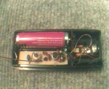 Here's a tiny one transistor spy FM transmitter bug that operates from a single 1.5V AA battery. Main advantage of this circuit is that power supply is a 1.5 Volts cell (any size) which makes it possible to fix PCB and the battery into very tight places. Transmitter even runs with standard NiCd rechargeable cells, for example a 750mAh AA size battery runs it about 500 hours (while it draws 1.4mA at 1.24V) which equals to 20 days. This way circuit especially valuable in amateur spy operations. Mini FM transmitters take place as one of the standard circuit types in an amateur electronics fan's beginning steps. When done right, they provide very clear wireless sound transmission through an ordinary FM radio over a remarkable distance. I've seen lots of designs through the years, some of them were so simple, some of them were powerful, some of them were hard to build etc.
Posted on Thursday, April 7, 2011 • Category: FM Transmitters
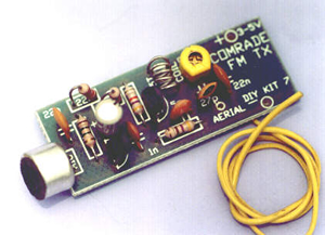 This FM transmitter is about the simplest and most basic FM transmitter it is possible to build and have a useful transmitting range. It is surprisingly powerful despite its small component count and 3V operating voltage. It will easily transmit over 300 meters in the open air and even more with higher voltage supply. The circuit we use is based on a proven Australian design. It may be tuned anywhere in the FM band. Or it may be tuned outside the commercial M band for greater privacy. Of course this means you must modify your FM radio to be able to receive the transmission or have a broad-band FM receiver. The output power of FM transmitter is within the legal limits of many countries. However, some countries may ban all wireless FM transmitters without a license. It is your responsibility to check the legal requirements for the operation and to obey them. FM transmitter is constructed on a single-sided printed circuit board PCB.
Posted on Tuesday, April 5, 2011 • Category: FM Transmitters
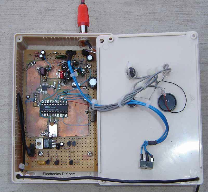 Here's a PLL FM Transmitter using LMX1601, ATtiny2313 or AT90S2313 microcontrollers. The common characteristic of all of the previous low power FM transmitters I've built over the decades, is that their operating frequency is determined by an LC resonant circuit. Some of them had excellent stability, some of them didn't, but I had always wanted to make one that is crystal controlled. Various schemes had been considered from time-to-time, including the direct approach of modulating the load capacitance of a a crystal oscillator, a whimsical phase modulation scheme involving a phase shifter, some balanced modulators, and limiting amplifiers, and at times, the down-to-earth and sober approach of modulating a VCO within a phase locked loop (PLL). While browsing Digikey's online catalog, I found the LMX1601 frequency synthesizer chip and thought: "Just maybe, the PLL approach is finally within my grasp."
The LMX1601, which apparently was designed for use in cell phones, includes everything need to make two phase locked loops except for the VCOs. More importantly, one of the PLLs, specifically the "AUX" PLL, is specified to work in the FM broadcast band. The LMX1600 and the LMX1602 were also considered, but the LMX1601 was selected because it has a "500 MHz option", meaning that it can work down to about 50 MHz.
Posted on Thursday, March 24, 2011 • Category: FM Transmitters
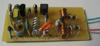 The FM telephone circuit is built on a PC board that is so small it can easily be fitted inside the housing of a telephone making it an instant pseudo-speak earphone. This FM transmitter circuit connects in series with telephone line, steals power from it, and transmits both sides of the conversation to an FM radio tuned between 90 and 95 MHz.
Posted on Friday, March 18, 2011 • Category: FM Transmitters
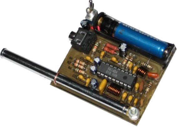 Circuit of stereo FM transmitter of of high quality using integrated circuit ba1404 for mp3, mp4, ipod, computer, radio of the car. Transmit of your equipment of portable audio for the radio of your car, transmitters of fm of low potency are the ideal for transmission wireless of audio sign for fm receivers. Mainly in that case that is treated of transmitter of FM stereo with ba1404.
The heart of that circuit is the circuit integrated ba1404, that is a mini fm transmitter, that already counts with the necessary internal circuits for transmission in fm. just being necessary to increase some components discman or any other audio source turning the wireless. If you already set up other transmitters of transistorized fm it will see that when setting up that with having integrated BA1404, that the quality of the sound and the frequency stability is excellent. Besides the but it presents easy assembly.
Posted on Friday, March 4, 2011 • Category: FM Transmitters
 The goal of this project is for me personally to learn a little more about fm transmitters and fm bug making (may the HAM radio gods bless me in this pursuit). The ideal outcome of this project is a very small and full functional FM transmitter that we can stick into a plastic mint box.
In order to be able to build this, we'll have to learn a lot about amplifiers, LC oscillators, mixers, antennas and FM. This project assumes you're already comfortable build your own PCB boards. If you're not please take a look at the homemade pcb's tutorial before you continue. It will help you out a lot.
Posted on Sunday, January 30, 2011 • Category: FM Transmitters
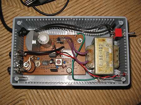 So, I needed a small transmitter, which would allow me to transmit good, old music into my AM-only radios. So, one saturday afternoon I got into gear, designed and built a very crude, terribly non-optimized little transmitter. It's almost a joke expressed in electronics, full of poor design, so please don't think that this is the best I can do! You must see it as a quick and dirty 5-hour effort, because that's all the time the transmitter took to design, build, and test. Making this web page about it is taking much longer! I'm putting this thing on the web only because many people have asked me to do so, despite its crude design!
Posted on Saturday, January 29, 2011 • Category: FM Transmitters
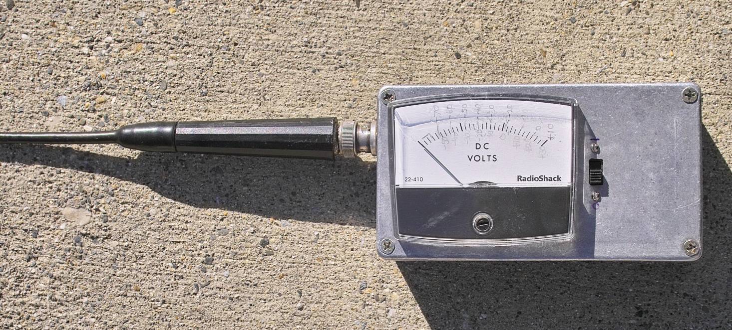 This unit is an updated version of the Wide Dynamic Range Field Strength Meter. While the basic function is the same, it has several critical differences:
It uses a specialized integrated circuit, the Analog Devices AD8307. This chip is designed specifically as a logarithmic amplifier for use through 500 MHz.
Using the AD8307, it has a wider dynamic range (85 dB versus 55 dB) and it has built-in temperature compensation.
Because of the different nature of this type of detector - and the fact that it has temperature compensation - means that there is no need for a "zeroing" control.
One disadvantage of this approach as compared to the diode approach is that the AD8307 has a lower frequency response than the diode. The frequency limit of the meter is dictated pretty much by the diodes themselves along with their physical layout and related components: There is no reason why the earlier version could not be constructed to work through 10 GHz or so - but the AD8307 is falling flat by the time you get to 1 GHz, making it unsuitable for detecting wireless LANs or PCS-type cell phones.
Posted on Thursday, January 27, 2011 • Category: FM Transmitters
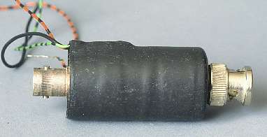 Everyone involved with radio transmitters needs some instruments to assess basic antenna functionality. Among these instruments, the best-known and most-used one is the Standing Wave Ratio meter. Some radio amateurs develop a cult for these little gadgets, having them in line all the time and watching the needles bounce while they chat. I have seen some guys owning 5 or 6 SWR meters, and no other instrument relating to antenna testing! While it's unfortunate that some people - specially amateurs - assign so much importance to SWR and so little to other parameters, it's also a fact that SWR needs to be known, so if you use transmitters, you need an SWR meter.
Posted on Wednesday, January 26, 2011 • Category: FM Transmitters
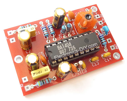 Be "On Air" with your own radio station! BA1404 HI-FI Stereo FM Transmitter - Special Edition Kit is an exciting transmitter that will broadcast high quality stereo signal in 88MHz - 108MHz FM band. It can be connected to any type of stereo audio source such as iPod, Computer, Laptop, CD Player, Walkman, Television, Satellite Receiver, Tape Deck or other stereo system to transmit stereo sound with excellent clarity throughout your home, office, yard or camp ground. Add 500mW FM / VHF Transmitter Amplifier / Booster for even longer range.
Special Edition BA1404 HI-FI Stereo FM Transmitter Kit includes premium components with audio grade gold capacitors, 1% Metal Film Resistors and quality PCB with Red Solder Mask and Plated-Through Holes. The kit is based on the popular BA1404 stereo broadcaster IC which contains all the complex circuitry for generating the stereo FM signal. 38 KHz crystal provides a rock solid stability of sub-carrier for stereo signal.
Posted on Wednesday, December 29, 2010 • Category: FM Transmitters
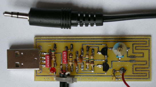 This small FM transmitter with a range of about 50 meters designed for connection to the USB port. With lots of mini-transmitters then you have a comprehensive, action-packed radio program. Due to the power supply via the USB port of a high frequency stability is achieved. Alternatively, the receiver, a battery 5 to 12 volts to operate.
Posted on Wednesday, December 29, 2010 • Category: FM Transmitters
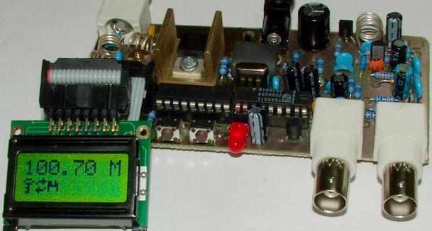 Easy to build high-quality PLL FM transmitter with typical output power of 5 W and no-tune design. The transmitter includes RDS/SCA input and Audio/MPX input with optional pre-emphasis. It can be used with or without stereo encoder. Tuning over the FM band is provided by two buttons that control dual-speed PLL. The transmitter can work also without the LCD display. Some experience with building devices of this kind are highly recommended.
Posted on Saturday, October 16, 2010 • Category: FM Transmitters
 This circuit is a circuit diagram fm transmitter. This circuit is somewhat different from the previous fm transmitter circuit. Transmitter circuit described here has the additional RF power amplifier stage, after the oscillator stage, to increase the power output of 200-250 milliwatts. With a good matching 50-ohm ground plane antenna or multi-element yagi antenna, this transmitter can provide a good enough signal strength to a distance of about 2 kilometers.
Posted on Thursday, October 7, 2010 • Category: FM Transmitters
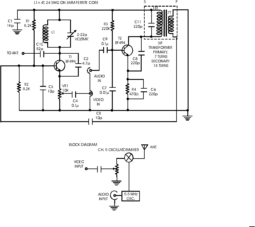
Posted on Thursday, October 7, 2010 • Category: FM Transmitters
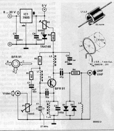 Simple oscillator that generates a frequency in the VHF or UHF region. The oscillator is modulated with the video signal and the modulated carrier wave thus generated is fed into the TV set's aerial input via a cable. Then all that remains to do is tune the TV to the correct frequency.
Posted on Thursday, October 7, 2010 • Category: FM Transmitters
 This handy prescaler divides input frequency by 1000. It takes maximum input frequency of 3.5GHz and converts it into 3.5MHz that may be measured using standard frequency meter.
Posted on Wednesday, October 6, 2010 • Category: FM Transmitters
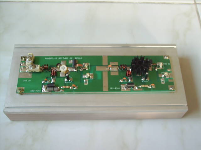 RF amplifier with 25W of power for 88-108MHz FM transmitters.
Posted on Wednesday, October 6, 2010 • Category: FM Transmitters
 The important part of the circuit is formed of the Colpitts type oscillator. C3,C4,C5,C6,CD1-CD2 and L1 determines the frequency. BF982 and dual gate MOSFET are active parts in oscillator. When the input impedance of the MOSFET gate inputs are high, LC tank is not affected. However transistors force the LC tank and cause phase shift. Two driver stages are added to isolate the antenna from oscillator. First stage (BF199) amplifies the low signal of the oscillator and works as a constant load. The second stage (BFR90) amplifies the signal going through the antenna some more. A short copper wire can be used as an antenna here. Attaching a large antenna to this circuit is unnecessary because the output power is low.
Posted on Wednesday, October 6, 2010 • Category: FM Transmitters
 Here is a simple set up which will enable them to measure the out put power of their transmitter. All that they require is a good multimeter which has a sensitivity of 20k ohms/4 Watts which is adequate for low power transmitters. Many beginners trying out their skill with QRP TX, for the first time have to overcome many problems before they are able to come on the air. On usual complaint is that, every thing is working fine but the signal is not going out.
Posted on Wednesday, October 6, 2010 • Category: FM Transmitters
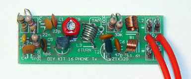 This FM transmitter attaches in series to one of your phone lines. When there is a signal on the line (that is, when you pick up the handset) the circuit will transmit the conversation. In particular it will radiate from the phone line itself. It is a passive device - there is no battery. It uses the signal on the phone line for power. No aerial is needed - it feeds back the RF signal into the phone line which radiates it in the FM band. The frequency of transmission may be adjusted by the trimcap.
Posted on Tuesday, October 5, 2010 • Category: FM Transmitters
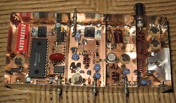 The PLL transmitter exciter has the functions of providing a stable, low noise, frequency-selectable RF signal and amplify it to a controllable output power sufficient to drive the power amplifier. It uses a PLL frequency synthesizer built with MC145151, which covers the FM band in 100kHz steps. The VCO covers only a few MHz without readjustment.
Posted on Tuesday, October 5, 2010 • Category: FM Transmitters
 The 30 watt amplifier schematic shown below provides an appropriate power boost with an input of 4 watt up to 6 watts. The circuit is designed to cover 88-108MHz FM Broadcast Band. However, the circuit is very stable at my place and provides a clean-output through seven (7) element Butter-worth low-pass filter.
Posted on Tuesday, October 5, 2010 • Category: FM Transmitters
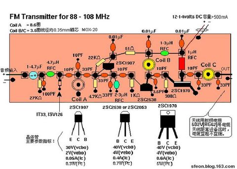 Presented is a three stage 3W FM Transmitter Amplifier using 2SC9018, 2SC2053 and 2SC1970 transistors. The circuit is supplied by 12-14V DC voltage and requires at least 500mA of current.
Posted on Tuesday, October 5, 2010 • Category: FM Transmitters
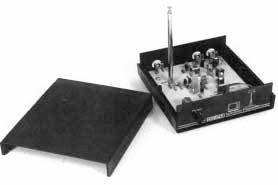 One of the most useful gadgets a video enthusiast can have is a low-power TV Transmitter. Such a device can transmit a signal from a VCR to any TV in a home or backyard. Imagine the convenience of being able to sit by the pool watching your favorite movie on a portable with a tape or laser disc playing indoors. You could even retransmit cable TV for your own private viewing.
Posted on Wednesday, September 15, 2010 • Category: FM Transmitters
 A amplifier of medium force RF for the FM, is always essential for the amateur that wants it strengthens some small transmitter, that likely it has already it manufactured! The present circuit can give force 25-30W, with control no bigger than 4-5 W.
As it appears in the analytic drawing, the amplifier is manufactured with the transistor TR1 of type LY89 of Phillips. The transistor this is specifically drawn for operation in frequencies up to 175Mhz, with very good results.
Posted on Tuesday, September 14, 2010 • Category: FM Transmitters
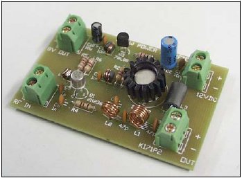 This project is a simple 2-transistor VHF power amplifier, with about 16dB gain, and requires no tuning or alignment procedures. Wideband techniques have been used in the design and the circuit is equipped with a "lowpass" filter to ensure good output spectral purity. The project has been designed for assembly on a single-sided printed circuit board. The circuit is specifically designed to amplify the output of 7mW to 10mW WBFM transmitters (wide band) to a final level of 250mW to 300mW.
Posted on Friday, September 3, 2010 • Category: FM Transmitters
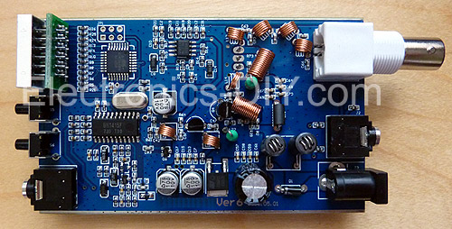 5W PLL Stereo FM Transmitter features PLL synthesized drift free operation with high quality BH1415 chip. 5W RF output power is achieved with 2SC1971 6W transistor in the output stage. Front panel digital control comes with LED display and case is made high quality aluminum. The board features EMI filtering on audio and power inputs and comes with Microphone and Audio inputs. Once transmitter is turned on it starts broadcasting with previously selected frequency. Overall this 5W PLL Stereo FM Transmitter provides professional broadcast audio quality and rivals commercial broadcasts.
Posted on Friday, September 3, 2010 • Category: FM Transmitters
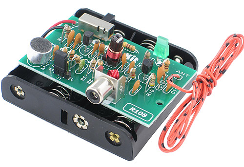 This is a unique FM transmitter that provides both a built-in sensitive microphone and an RCA jack for line input. It has two modes of operations, "Microphone" and "Line", which are selectable using a jumper. In the "Microphone" mode, it can be used as a wireless microphone transmitter. In the "Line" mode, it can be easily connected to any audio source to broadcast the audio signal to any FM receiver within its range. 500mW FM / VHF Transmitter Amplifier / Booster can be added for longer transmission range.
Posted on Friday, September 3, 2010 • Category: FM Transmitters
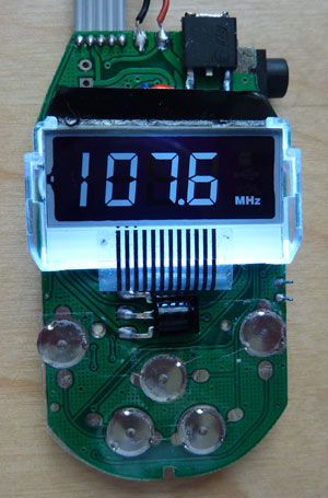 Features PLL tuned transmitter / exciter for rock solid frequency stability over the entire FM band. Displays Transmitted Frequency on backlighted LCD. PCB includes antenna output to which a piece of wire, or VHF amplifier can be connected for greater transmission range. Includes 3.5mm audio jack cable. Plays MP3 from SD and USB memory (SD and USB connectors on board). IR Remote can be used to control the transmitter.
Posted on Friday, September 3, 2010 • Category: FM Transmitters
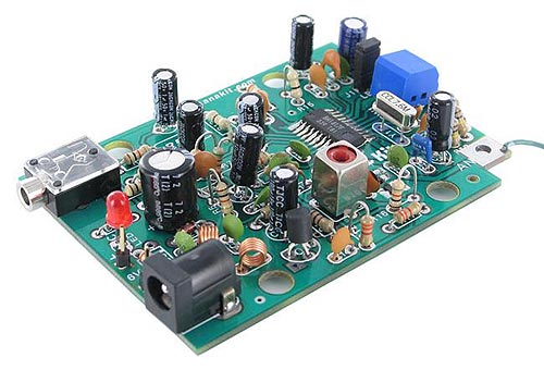 This is a high quality stereo PLL FM transmitter incorporating a Phase-Locked-Loop (PLL) synthesizer. It is based on the Rohm BA1417 PLL FM Transmitter Integrated Circuit and offers a choice of up to 14 preset transmission frequencies spaced every 200 KHz between: 88.7 – 88.9 MHz (Low Band Mode) and 106.7 – 107.9 MHz (High Band Mode). It has outstanding frequency stability thanks to the PLL crystal controlled design and offers excellent high-fidelity audio performance.
It is ideal for use in your home or office to transmit MP3 songs or internet radio stations from your computer to any standard FM radio. It can also be connected to any other audio source, such as an iPod, a MP3 Player, Walkman, Discman or XM Satelite Radio receiver.
The circuit incorporates a stereo audio input jack as well as a DC adapter jack which makes it quick and easy to setup. Transmission frequency selection is done through a DIP switch.
Posted on Thursday, August 5, 2010 • Category: FM Transmitters
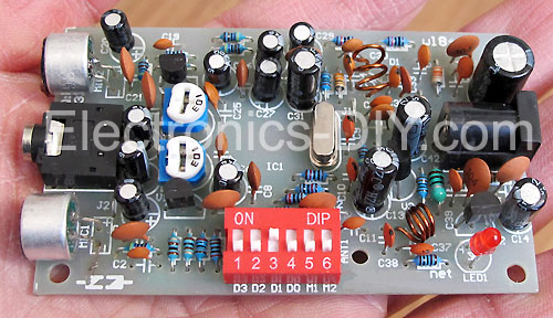 This is an excellent 50mW Hi-Fi PLL FM Stereo Transmitter that features BH1417 chip. ROHM's new Japan has BH1417 is one of the most simple and practical integrated circuits, which combines phase-locked loop circuit, stereo encoder circuit, transmitter circuit, as well as other additions. Pre-emphasis circuit, limiter circuit and low pass filter can significantly improve the sound quality. The total harmonic distortion up 0.3%, stereo separation to 40dB, RF output level is 100dB. BH1417F is an excellent new IC chip, this circuit improves signal to noise ratio (S / N) of pre-emphasis circuit to prevent signal over emphasized limiting circuit, the control input signal frequency low-pass filter circuit (LPF), generate stereo stereo composite signal modulation circuit, FM transmitter phase-locked loop circuit (PLL) component. BH1417F excellent frequency characteristics, it can achieve 40dB of isolation, transmitted sound quality is similar to local FM radio stations.
Posted on Thursday, August 5, 2010 • Category: FM Transmitters
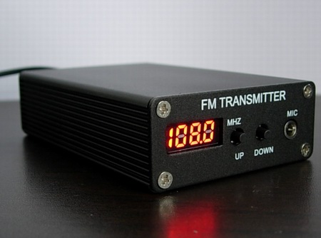 5W PLL Stereo FM Transmitter features PLL synthesized drift free operation with high quality BH1415 chip. 5W RF output power is achieved with 2SC1971 6W transistor in the output stage. Front panel digital control comes with LED display and case is made high quality aluminum. The board features EMI filtering on audio and power inputs and comes with Microphone and Audio inputs. Once transmitter is turned on it starts broadcasting with previously selected frequency. Overall this 5W PLL Stereo FM Transmitter provides professional broadcast audio quality and rivals commercial broadcasts.
Posted on Thursday, July 15, 2010 • Category: FM Transmitters
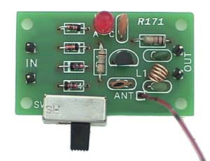 This Phone FM transmitter connects in series to your telephone line and transmits the telephone conversation over the FM band when you pick up the telephone handset. Transmitted signal can be tuned by any FM receiver. The circuit includes an "On Air" LED indicator and also provides a switch which can be used to turn off the transmitter. A unique feature of the circuit is that no battery is needed to operate the circuit since power is taken from the telephone line. The transmitter uses only a short piece of wire aerial about 4" / 10 cm long to transmit the signal and some of the RF signal is also radiated through the telephone line itself. The circuit might be used to share or record conversations, but is not intended for illegal use.
Posted on Thursday, July 8, 2010 • Category: FM Transmitters
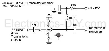 This is a high performance low noise 500mW amplifier / booster for all low power FM transmitters such as BA1404, BH1417, BH1415, 433MHz transmitter modules, etc. The amplifier chip is an integrated circuit containing multiple transistor stages and all other parts conveniently within a single small package. Boosting your FM transmitter has never been easier and the output signal can also directly drive 2n4427 or 2n3886 transistors for 1W or 5W of RF output power.
Posted on Saturday, June 12, 2010 • Category: FM Transmitters
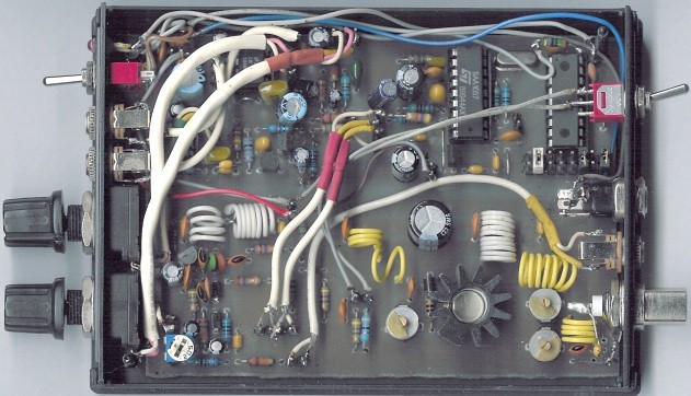 This small FM transmitter includes a limiter, a microphone amplifier and a PLL digital tuning. All the parts are placed on one circuit board. The RF power is switchable between 1W and 0,2W.
The schematic diagram is divided into three parts: RF part (numbered from 1), PLL (numbered from 30) and audio part (numbered from 50).
Posted on Saturday, June 12, 2010 • Category: FM Transmitters
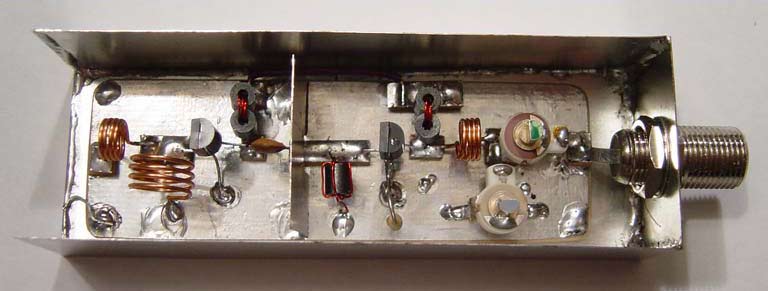 The TX500 is a simple to build 500mW FM Transmitter. It consists of three blocks; modulator / oscillator, two stage 500mW VHF amplifier and LED based power meter. The TX500 allows to transmit audio signals to FM band at frequencies from 88 MHz to 108 MHz. Due to the very low power consumption of less than 100mA the circuit may be perfectly powered by using 9-12V battery or power supply if you prefer. The circuit has been divided into separate stages so that it is be better for everyone to understand how every part works independently.
Posted on Saturday, June 12, 2010 • Category: FM Transmitters
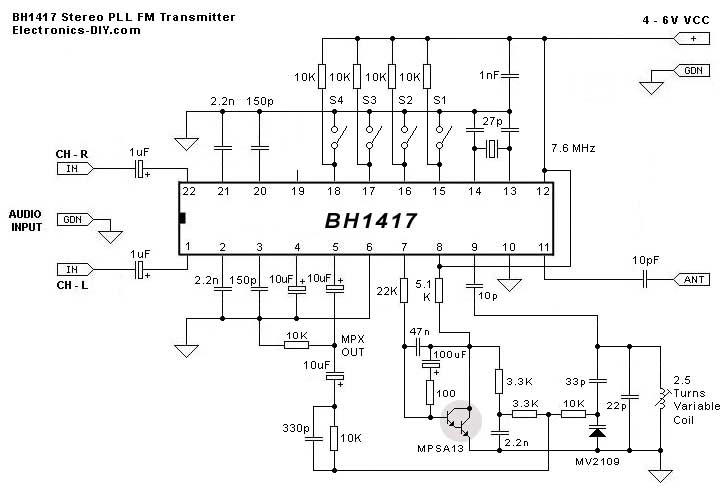 BH1417 is a latest FM Transmitter IC from RHOM that includes a lot of features in one small package. It comes with pre-emphasis, limiter so that the music can be transmitted at the same audio level, stereo encoder for stereo transmission, low pass filter that blocks any audio signals above 15KHz to prevent any RF interference, PLL circuit that provides rock solid frequency transmission (no more frequency drift), FM oscillator and RF output buffer.
Posted on Saturday, May 22, 2010 • Category: FM Transmitters
 This FM transmitter circuit uses four radio frequency stages: a VHF oscillator built around transistor BF494 (T1), a preamplifier built around transistor BF200 (T2), a driver built around transistor 2N2219 (T3) and a power amplifier built around transistor 2N3866 (T4). A condenser microphone is connected at the input of the oscillator.
Posted on Thursday, May 6, 2010 • Category: FM Transmitters
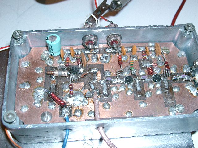 This page describes TX ATV Transmitter for 23 cm with output adjustable from 100 to 250mW.
Posted on Friday, April 30, 2010 • Category: FM Transmitters
 This new FM transmitter is very simple and doesn't need any RF tuning.
First of all ,we have used an integrated VCO: The POS150 from Mini-circuits.
This excellent RF circuit covers all the FM Band in a voltage range of 4V to 8V.
The Kvco factor is very stable all over the FM band, consequently, we have applied the BF signal directly on the control voltage line coming from the PLL.
Posted on Friday, April 30, 2010 • Category: FM Transmitters
 The functioning of all is provided by a microcontroller from MICROCHIP "PIC16F84" which provides support for buttons, LCD 2 lines of 16 characters and the circuit pll "SAA1057.
The VCO is entrusted to the transistor Q8 associate of his two diodes varicaps "BB109, a floor buffer Q7 separates the VHF signal obtained in two ways, on the one hand to Q9 to enslave loop phase and on the other hand to the Q5 and Q6 together which takes care to amplify the signal before attacking Q11, a "BFR96" which plays the role of HF switch via a timer "NE555" which receives information from the push and "SAA1057" ensuring HF cutoff in the event of failure of a locking or unlocking of the pll.
Posted on Friday, April 30, 2010 • Category: FM Transmitters
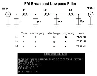 Filter used for eliminate unwanted harmonic frequency at second and third. Notch filter, Band Pass Filter (BPF), and High Pass Filter (HPF) sometime combined in constructing LPF design.
Schematic below for FM Broadcast Lowpass Filter 88-108 MHz. It has been tested with a good result.
Note : Make the coils at 74 nH and trim them to adjust exact value.
Posted on Thursday, April 29, 2010 • Category: FM Transmitters
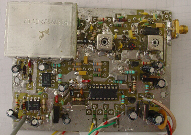 In order to simplify the transmitter design, we've used the new pll circuit from Motorola :the MC145170.
This PLL includes the prescaler and a serial standard bus called SPI.
Posted on Wednesday, April 28, 2010 • Category: FM Transmitters
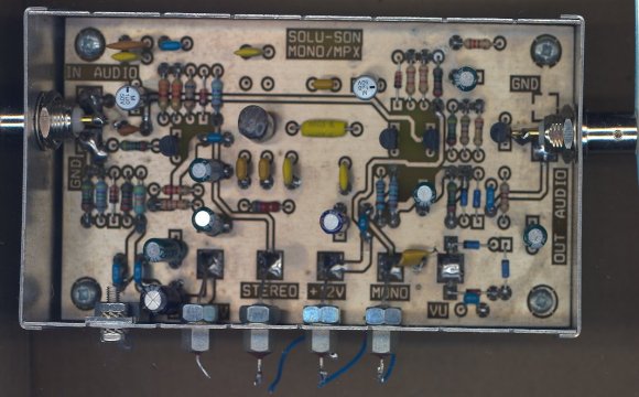 This map, armored also enables automatic MONO / MPX through a low-pass filter, even with a multiplex on its entry by using an ON / ON, panning, the whole spectrum MPX more RDS is sent to the synthesizer, on the other hand when it is in a position MONO, the low-pass filter is activated and share its cutoff frequency at 15 KHz, only modulation G + D is sent to the synthesizer, as 19 KHz. 19 KHz carrier, the signal multiplex and subcarrier 57 KHz is thereby eliminated, which provides ease of use for example in a string of issue relay tuner, if the link between the issuer Departure and receiver re-issue was not of good quality stereo, you sufficient to switch to mono to improve sound quality, you can then connect the RDS encoder at the re-issuer.
Posted on Friday, April 23, 2010 • Category: FM Transmitters
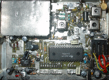 This PLL has been designed with an old Motorola circuit :the MC145151.
The VCO is based on a "Colpitz" oscillator equiped with a Fet Transistor.(J310)
Two varicap Diodes are used in order to reduce the global noise of the VCO.
In addition,these two diodes allow the PLL to keep the lock status through a large range of climatic conditions.
An another J310 is used in order to match the impedance between the oscillator and the fist amplifier stage.
A MSA1105 from Minicircuits increases the RF power level coming from the VCO to +14dBm.
A simple low pass filter rejects the second harmonic to -20 dB.(Worst case)
Finally, a 7 dB attenuator and a second amplifier stage (BFR96S) achieve this radio design.
Posted on Friday, April 23, 2010 • Category: FM Transmitters
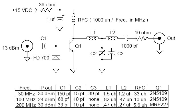 This is a universal 1 Watt RF class C amplifier that is ideally suited for low power FM transmitters. Input should be at least 100mW to achieve 1W output. It is recommended to enclose the amplifier in a metal case.
Posted on Thursday, April 22, 2010 • Category: FM Transmitters
 This page describes TX ATV Transmitter for 23 cm with output adjustable from 100 to 250mW.
Posted on Saturday, April 10, 2010 • Category: FM Transmitters
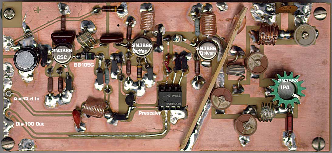 This is a PLL controller that works with the VCO/Modulator that I designed. Use these two modules together for a complete baseband-capable exciter unit. This PLL controller features a rock-stable crystal controlled reference, in conjunction with a programmable dividing network which allows the transmitter to be tuned in 100Khz steps from 79.9Mhz to 109.7Mhz by means of digital thumbwheel switches. Oscillator, buffer and driver stages use 2N3866 power RF transistor and output stage used 2N3553 4W RF transistor,
Posted on Friday, February 19, 2010 • Category: FM Transmitters
 This MP3 Player FM transmitter can be used to listen to your own music throughout your home. The transmitter circuit use no coils that have to be wound. When this FM transmitter used in the car, there is no need for a separate input to the car stereo to play back the music files from your MP3 player.
This FM transmitter use a chip made by Maxim Integrated Products, the MAX2606. The VCO (Voltage Controlled Oscillator) in this IC uses a Colpitts oscillator circuit. The variable-capacitance (varicap) diode and feedback capacitors for the tuning have also been integrated on this chip, so that you only need an external inductor to fix the central oscillator frequency. The supply voltage to the IC should be between 2.7 and 5.5 V, the current consumption is between 2 and 4 mA.
Posted on Friday, February 19, 2010 • Category: FM Transmitters
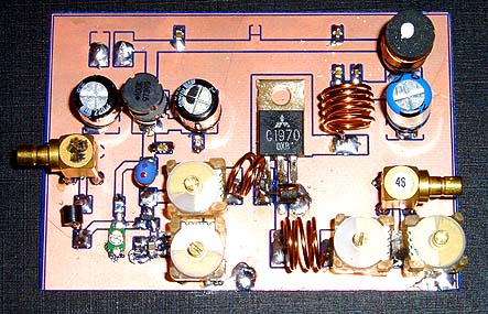 This RF power amplifier is based on the transistor 2SC1970 and 2N4427. The output power is about 1.3W and the input driving power is 30-50mW. It will still get your RF signal quit far and I advice you to use a good 50 ohm resistor as dummy load. To tune this amplifier you can either use a power meter/wattmeter, SWR unit or you can do using a RF field meter.
Posted on Friday, February 19, 2010 • Category: FM Transmitters
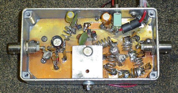 This design is a 2 stage amplifier that has about 17db of gain, suitable for an input of 50 to 100 MW. Its basically a Veronica 5 watt vco transmitter, without the vco. The transistors are a 2N4427 and a MRF237. Output power is 2.5 to 5 watts, depending on input drive and dc voltage. At 13.7 vdc with 50 MW of drive, the output was 2.5 watts. The maximum dc voltage recommended is about 15-16 volts.
Posted on Saturday, October 31, 2009 • Category: FM Transmitters
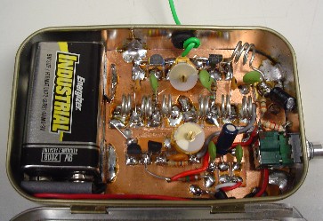 The transmitter uses 2 MPSH10 (equiv BF494 or NTE229) transistors in a double-ended free-running voltage controlled oscillator (VCO) operating at half the output frequency on each side and combined at L2, which is tuned to the 2nd harmonic of the VCO and covers the 88-108 MHz range. A standard 9 volt battery is used for power and fits inside the tin. The mono audio input circuit is totally passive with 70us pre-emphasis provided and the audio quality is great.
Posted on Thursday, October 29, 2009 • Category: FM Transmitters
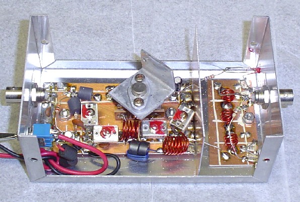 This is a 1 watt amplifier. This design is a 2 stage amplifier that has about 16db of gain, suitable for an input of 5 to 20 MW. The transistors are a 2N4401 and a 2N4427. At 13.7 vdc the most I could get out of the unit was 1/2 watt, you could probably raise the dc voltage to 16 volts and get more output but then a much better heatsink would be required. But for the sake of this project, we'll call it a 1/2 watt amplifier.
Posted on Tuesday, October 27, 2009 • Category: FM Transmitters
 The achievement of this 30-watt amplifier has been designed to take place on a heatsink microprocessor PC equipped with its fans, the advantage of this method of cooling has been selected for the fact that it is not very common and expensive. The size of the printed circuit will adapt quite easily to the type of heatsink as you have available, if possible, because in many cases, those of recovery, the fans have already lived and the price of a model remains very affordable.
Posted on Tuesday, October 27, 2009 • Category: FM Transmitters
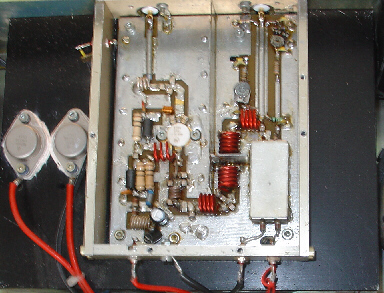 This Power amplifier is equipped with a bipolar transistor,the famous MRF317 As lots of FM amplifier application ,the power transistor is in a C class bias. All the impedance networks (Input & Output) have been determined by using the software: Mimp.EXE. A 9 elements low pass filter ensures that we meet at least a 60 dB rejection from the carrier.(RF Simulation with RFSIM99) The FM amplifier has a 10 dB gain with a 60 to 65% efficiency. The Input VSWR is around 1.4 and there's no problem to reach the max power in all the FM band.
Posted on Tuesday, October 27, 2009 • Category: FM Transmitters
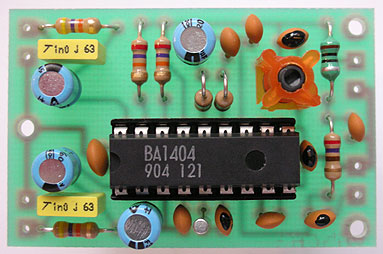 Be "On Air" with your own radio station! BA1404 based transmitter is an exciting product that will broadcast high quality stereo signal in 88MHz - 108MHz FM band. It can be connected to any type of stereo audio source such as iPod, Computer, Laptop, CD Player, Walkman, Television, Satellite Receiver, Tape Deck or other stereo system to transmit stereo sound with excellent clarity throughout your home, office, yard or camp ground.
Posted on Tuesday, October 27, 2009 • Category: FM Transmitters
 That RF Amplifier is for boosting small fm transmitters and bugs. It use two Philips 2N4427 and its power is about 1Watt. At the output you can drive any linear with BGY133 or BLY87 and so on. Its power supply has to give 500mA current at 12 Volts. More voltage can boost the distance but the transistors will be burned much earlier than usual.! In any case do not exceed the 15Volts. The Amp offers 15 dB in the area of 80Mhz to 110 Mhz. L4, L5, and L6 are 5mm diameter air coils, 8 turns, with wire 1mm wire diameter.An easy project, with great results.
Posted on Saturday, August 22, 2009 • Category: FM Transmitters
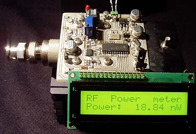 This watt meter project is very similar to my last wattmeter project. The main reason I made a new project is becasue I needed a unit which could handle higher power than 1W. I found a 50 ohm dummy load which could take 50W of power. Of course I could use attenuates for my 1W meter, but I prefered to build a new unit. The new thing with this project is that it will only display the power in Watt on the LCD display.
Posted on Monday, November 10, 2008 • Category: FM Transmitters
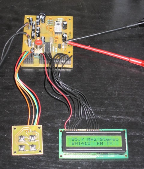 Here is a stereo FM Transmitter based on BH1415F wireless audio link IC. Phase Locked Loop controller use Microchip PIC16F628 and the the PLL frequency programming can be displayed with 8×2 and 16×2 LCD display. The frequency range can adjustable from 88-108 MHz.
Posted on Monday, November 10, 2008 • Category: FM Transmitters
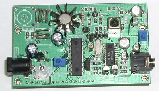 This is FM PLL Stereo based BH1415F IC from Rohm, it's has built in PLL and Stereo Encoder. You can download the schematic, pcb layout and Hex code. The transmitter menu display with LCD, and this have step 100Khz, 200Khz,.....1000Khz and have Mode menu (stereo/mono). In Action, LCD Display can solder directly on the bottom.
Posted on Tuesday, May 6, 2008 • Category: FM Transmitters
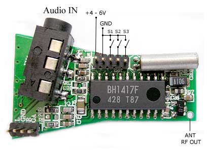 This is a high quality PLL Stereo FM Transmitter with build-in VHF amplifier for longer transmission range. It is based on BH1417 chip that offers high quality crystal clear stereo transmission. Eight available frequencies are controlled by grounding S1, S2 and S3 pins on header connector. Includes, high quality ROHM BH1417 transmitter chip, on-board amplifier increases transmission range, uses 7.6MHz crystal for rock-solid PLL FM transmission, crystal based Stereo Encoder and 3.5 standard audio input jack.
Posted on Thursday, April 24, 2008 • Category: FM Transmitters
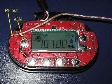 Many people prefer to listen to their own music (or voice) on radio.
This project explain how you can build and connect a powerful 1W amplifier to your FM transmitters.
A perfect solution for those wishing to listen to their favorite tunes in the car, house, garden,
school, campus, party, you name it....
Why not share your music with every one else in your city!
Posted on Thursday, April 24, 2008 • Category: FM Transmitters
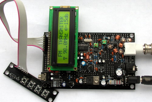 BH1415F FM Stereo PLL Transmitter
Transmitter power amplifier, the output signal from BH1415F by 2 SC9018, 2SC3355, 2SC2053 amplified signal can reach more than 500 mW, adjusting well to achieve greater power. Measured by the pull rod antenna used to be launched in the open 800 meters above. Uses external antenna will be launched even further. attention in 2053 need to be installed and tested at the load connected to leave, or else very easily burn 2053, 50 European amateur production of 2 W can be used instead of resistance. installed and tested at three levels circuit can be installed and tested.
Posted on Wednesday, April 23, 2008 • Category: FM Transmitters
 A simple FM transmitter links your home-entertainment system to a portable radio that can be carried around the house and into the back yard. For example, you can play music on the CD changer in your living room, and listen to it on a portable radio by the back-yard barbeque.
IC1 is a voltage-controlled oscillator with integrated varactor. Its nominal frequency of oscillation is set by inductor L1, and a 390nH value places that frequency at 100MHz. Potentiometer R1 then lets you select a channel by tuning over the FM band of 88MHz to 108MHz. Output power is about -21dBm into 50 (most countries accept emissions below 10dBm in the FM band).
The home system's left and right audio signals are summed by R3 and R4, and attenuated by the (optional) potentiometer R2. R2's wiper signal serves as a volume control by modulating the RF frequency. Signals above 60mV introduce distortion, so the pot attenuates down from that level.
In the absence of a standard FM radio antenna, 75cm (30 inches) of wire will suffice as a transmitting antenna. For best reception, it should be mounted parallel with the receiving antenna. The IC operates on a single supply voltage in the range 3V to 5V, but you should regulate the applied voltage to minimize frequency drift and noise.
Posted on Sunday, April 20, 2008 • Category: FM Transmitters
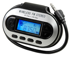 Now you can use your MP3 Player to listen your favorite tunes through any FM stereo receiver. Wireless FM transmitter wirelessly connects portable music players to your car or home stereo quickly and easily. Just plug the FM Transmitter into the headphone jack of your MP3 or any audio source including iPOD, PDA, CD Player, Cassette player or connect it to your PC or laptop computer. Tune your card stereo or receiver to the clearest FM frequency, and enjoy your digital music with full sound and convenience.
Features:
- PLL tuned transmitter / exciter for rock solid frequency stability over the entire FM band
- Displays Transmitted Frequency on blue backlighted LCD
- 100KHz frequency increments
- Includes three frequency memory buttons
- PCB includes antenna output to which a piece of wire, or standard VHF amplifier can be connected for greater transmission range
- Uses PLL synthesizer chip up to 1.4GHz
- Includes 3.5mm audio jack cable
- Small size
Posted on Tuesday, April 15, 2008 • Category: FM Transmitters
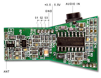 This is a high quality PLL Stereo FM Transmitter with build-in VHF amplifier for long transmission range. It is based on BH1417 chip that offers high quality crystal clear stereo transmission. Eight available frequencies are controlled by grounding 3 pins on header connector. This transmitter comes assembled and is ready to use.
Features:
- Two on-board transistors increase transmission range
- Uses 7.6MHz crystal for rock-solid PLL FM transmission
- Crystal based stereo encoder
- Very small size
Posted on Monday, April 14, 2008 • Category: FM Transmitters
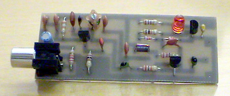
Here is the latest and greatly improved TX200 VFO/VCO FM transmitter. The most versatile transmitter to date that can be turned into high fidelity stereo PLL based 200mW FM transmitter. It is a perfect circuit for transmitting your music around the house and yard. TX200 uses only two coils; one in the oscillator and the other one in the 200mW VHF amplifier so it should be fairly easy for anyone to build. It also includes built-in pre-emphasis and C5 for enhanced sound quality. While assembling the transmitter care must be taken to make sure that C1 is directly connected to L1 and C9 to L2. These caps eliminate the distortions form the DC supply and improve the sound quality greatly. 9V voltage supply is also very important because it provides the exact amount of current to Q1 to produce loud and clear sound quality.
Posted on Thursday, April 10, 2008 • Category: FM Transmitters
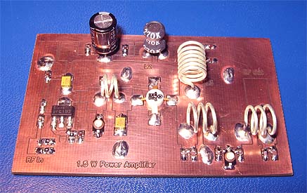 This project will explain the basic function of a class-C transmitter. I will explain how to dimension a transmitter and the purpose of the different components. I will also explain how you can build a 1.5W PA transmitter. The project will include PCB, components and instructions how to make coils, assembly and testing.
Posted on Thursday, April 10, 2008 • Category: FM Transmitters
 This is the latest BH1417 FM Transmitter design from RHOM that includes a lot of features in one small package. It comes with pre-emphasis, limiter so that the music can be transmitted at the same audio level, stereo encoder for stereo transmission, low pass filter that blocks any audio signals above 15KHz to prevent any RF interference, PLL circuit that provides rock solid frequency transmission (no more frequency drift), FM oscillator and RF output buffer.
There are 14 possible transmission frequencies with 200KHz increments that users can select with a 4-DIP switch. Lower band frequencies start from 88.7 up to 89.9 MHz, and upper band frequencies start from 107.7 up to 108.9 MHz.
Posted on Tuesday, April 8, 2008 • Category: FM Transmitters
Very stable FM transmitter based on TSA5511 synthesizer. Frequency is performed with three buttons through PIC16F84 microcontroller. Frequency is displayed on 16×1 LCD.
Posted on Wednesday, April 2, 2008 • Category: FM Transmitters
Be "On Air" with your own radio station! BA1404 based transmitter is an exciting product that will broadcast a high quality stereo signal in the 88 – 108MHz FM band. It can be connected to any type of stereo audio source such as personal computer, CD player, Walkman, television, tape deck or stereo system to transmit stereo sound with excellent clarity throughout your home, office, yard or camp ground.
Circuit-Zone.com © 2007-2026. All Rights Reserved.
|
|
|