Circuit-Zone.com - Electronic Projects
Posted on Sunday, December 29, 2013 • Category: LED
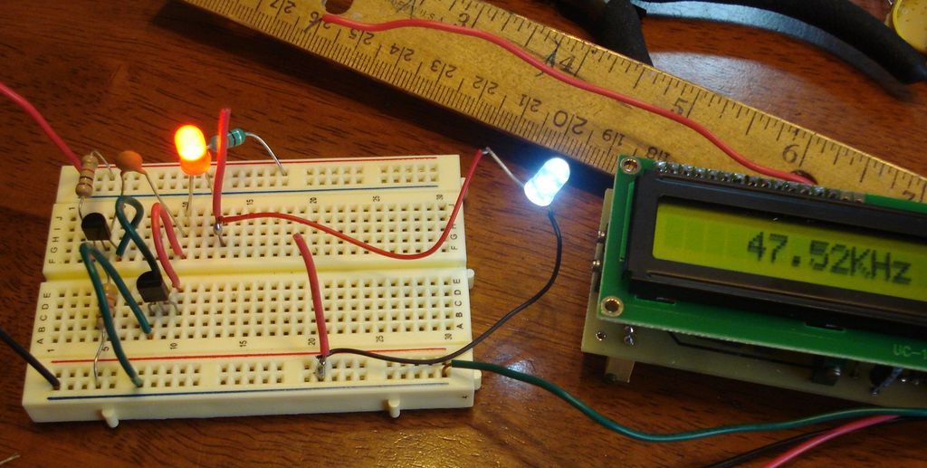
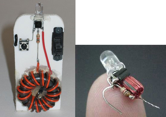
The "Joule Thief" circuit that does not use a transformer to power LED from a single 1.5V battery cell. The circuit consists of two bipolar transistors, coil, two resistors and capacitor to generate higher voltage through 50KHz frequency to power an ordinary LED. Entire circuit draws only about 15 milliamps.
Posted on Friday, December 13, 2013 • Category: LED
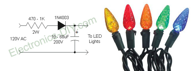 I like the idea of using LED Christmas lights because they look cool and consume very small amount of electricity, but the flicker drives me crazy! That's because they are powered directly from 110V AC voltage instead DC voltage which makes them flicker 60 times per second. Here is a simple circuit that will completely eliminate LED Christmas lights flicker. The solution is to convert AC to DC voltage with resistor, rectifier diode and capacitor. Using 470 ohm - 1K resistor is very essential because it limits the current to 20mA and minimizes the voltage to about 80 volts. If we didn't use the resistor LEDs would be powered by over 50mA of current which is much more than what they need and that would definitely shorten their life. Note that lowering voltage does not reduce the brightness of the LEDs because when powered by DC voltage they are always on.
Posted on Tuesday, January 24, 2012 • Category: LED
 Here is a circuit for simulating breathing / pulsing LED with the 555 timer chip. It became very popular and i received many comments and emails with people that made this circuit and worked fine, as well as comments with people that had troubles converting it to operate at 12 volts supply. It was designed to operate with 5 volts, because i plan to use it for a future PC mod. Since the PC power supply has 5 volts output, and since the LEDs that i plan to use require 3.8 volts to operate, choosing 5 volts for supply was the best choice to minimize power dissipation on the transistor.
Posted on Monday, July 18, 2011 • Category: LED
 Here's a simple circuit that flashes an LED on and off. This circuit uses the 555 timer in an Astable operating mode which generates a continuous output via Pin 3 in the form of a square wave. This turns the LED (D1) on and off. The speed at which the LED (D1) is turned on and off is set by the values of R1 and R2.
Posted on Friday, June 24, 2011 • Category: LED
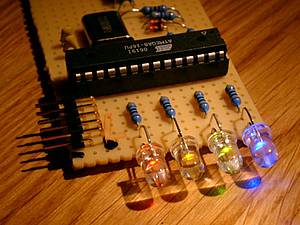
 Here's a simple running LEDs circuit based around PIC 12F675. I'm begin in developer with MCUs and recently i bought some eletronics components. Then i using Proteus for assembling the circuit and MikroC for developer MCU. I am making the leds blink using PIC12F675, 4 resistors 220 ohm and 4 leds.
Posted on Wednesday, May 25, 2011 • Category: LED
 The circuit is a LED flasher to light LED with single 1.5V battery is usually based on a blocking oscillator or a charge-pumped voltage doubler.This is another (but similar to charge pump) way to flash LED with 1.5V battery. The base-R voltage becomes nearly double the Vcc while making oscillation timing of astable multivibrator. LED can be flashed if it is attached aside. Since the LED discharges the C electricity, oscillator timing is shortened.
Posted on Friday, May 20, 2011 • Category: LED
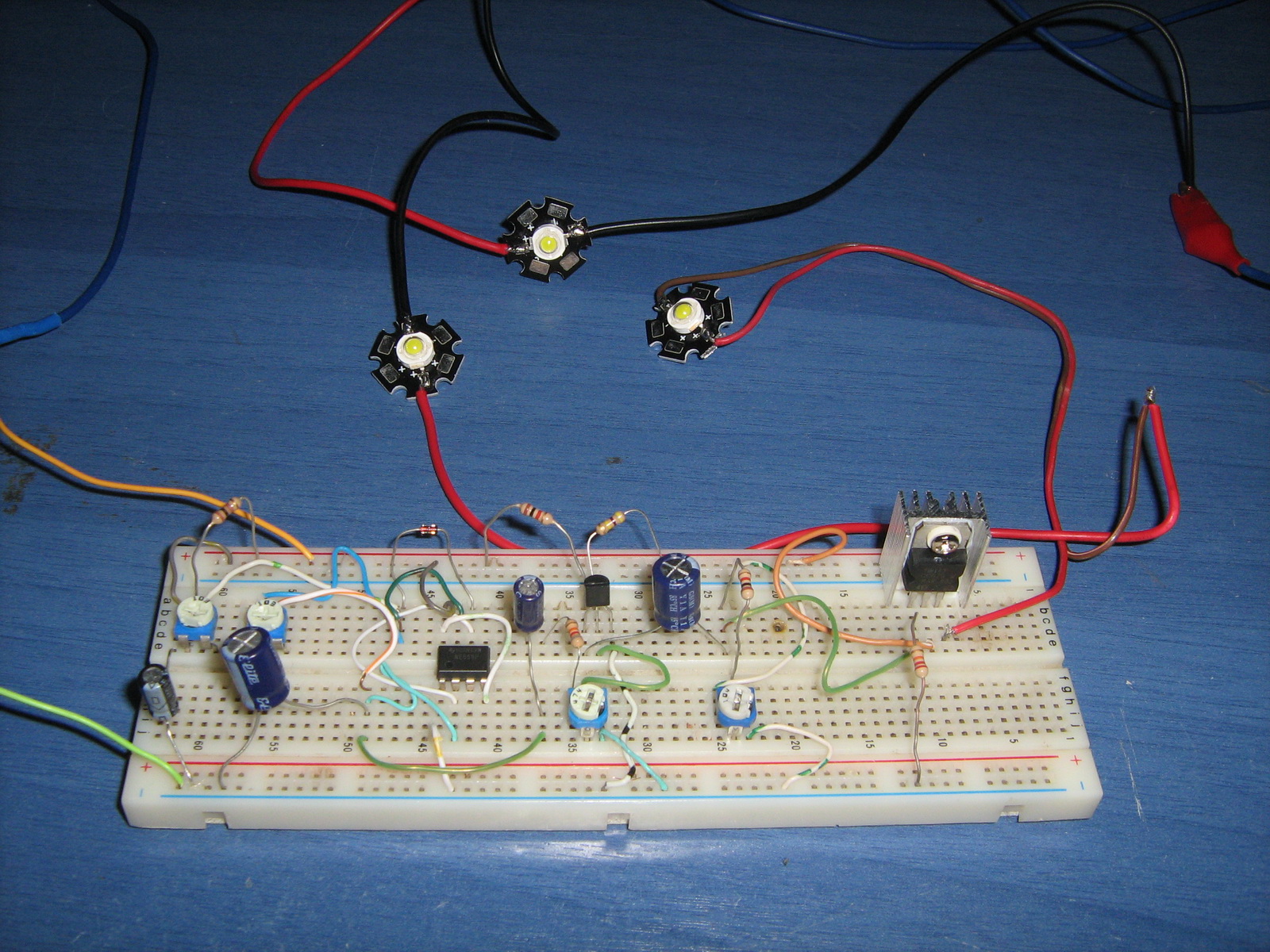
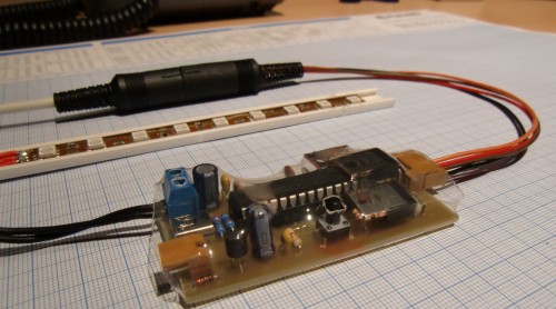
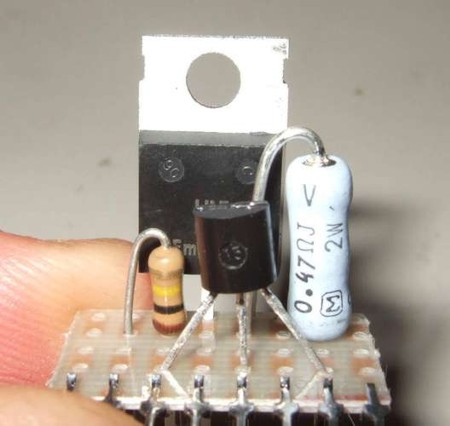 Here's a really simple and inexpensive Power LED driver circuit. The circuit is a "constant current source", which means that it keeps the LED brightness constant no matter what power supply you use or surrounding environmental conditions you subject the LED's to.
Or to put in another way: "this is better than using a resistor". It's more consistent, more efficient, and more flexible. It's ideal for High-power LED's especially, and can be used for any number and configuration of normal or high-power LED's with any type of power supply.
As a simple project, i've built the driver circuit and connected it to a high-power LED and a power-brick, making a plug-in light. Power LED's are now around $3, so this is a very inexpensive project with many uses, and you can easily change it to use more LED's, batteries, etc.
Posted on Wednesday, May 18, 2011 • Category: LED
 The USB-LED-Fader is a device to control a number of LEDs via USB. I built it to display the online status of my internet connection, the recording status of my video recorder (VDR), and warnings if the available disk-space is low. You can imagine an endless number of applications for this.
The LEDs are controlled with pulse width modulation (PWM). That way, they are not only on or off, it is possible to control the brightness. Included in the device are a number of 'waveforms' that can be displayed through the LEDs. That way, one LED can display some kind of a sine- or triangular wave without any interaction with the controlling host.
Every LED can be controlled individually; each one can display its own waveforms.
Posted on Friday, May 6, 2011 • Category: LED
 This the circuit light led flashing ,with show of 10 LED. By use integrated number circuit CD4017 perform be Decade Counter/Divider with 10 Decoded Outputs. Which it is integrated digital circuit CMOS then use the power supply about 9VDC. For a signal input continue the circuit can produce general frequency may use IC NE555 all right.
Posted on Wednesday, April 6, 2011 • Category: LED
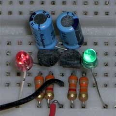
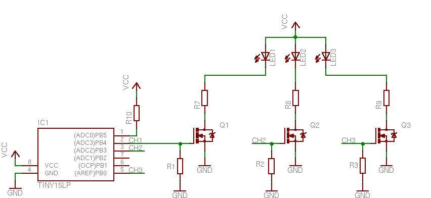 Power RGB LED Controller is the extension of tiny RGB to drive high power LED’s. For this project I used a 3 x 1W common Anode RGB LED. Q1 to Q3 are N-Channel HEXFet Mosfet’s with logic level drive and a RDSon at about 50mOhms. R1 to R3 are at about 2k2, R4 to R6 at about 15k and R7 to R9 depend on the LED used and VCC. If you use FET’s with higher RDSon you have to consider RDS in your calculation!
Posted on Saturday, March 26, 2011 • Category: LED
 This is great LED-controller board with lots of handy features. USB interface allows selecting operating modes directly on your PC screen without need additional input devices on boars. Project has preprogrammed several modes including slow and fast color change, temperature base color ,where color depends on temperature measured from temperature sensor (DS1821). Other modes include constant colors that can be configured with C# Win application. Actually there are more possibilities of usage especially when USB is used. Write your own or use PC application that would represent CPU load or other content with RGB colors. Project is built around PIC18F2550 microcontroller which comes along with USB interface. So USB requires couple elements what allows focusing on other parts of circuitry.
Posted on Friday, March 25, 2011 • Category: LED
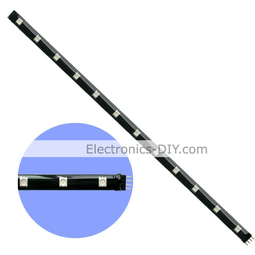 These flexible waterproof RGB LED strips contain 12 Ultra Bright RGB LEDs on 30cm strip. RGB LEDs can produce Ultra Bright White, Red, Green, Blue, Violet, Cyan & Yellow light. LED strips have durable and waterproof design and can be used for cars, trucks, motorcycles, garden decoration, cabinets, Audio / Video systems, home theaters, computer, etc. They include double-sided self-adhesive tape that can be used to attach to cabinets and other surfaces. RGB LED strip includes 4-PIN female connector at each end and one 4-PIN male connector to connect multiple RGB LED strips together (no soldering is required). Simply connect 12V DC power supply and you are ready to go.
Posted on Monday, March 21, 2011 • Category: LED
 In this page we will introduce a great project designed by Toon Beerten. This project can become a very interesting add-on for your room that's absolutely sure it will impress everyone. As you can see on the photos, we talk about a color fading lamp, that looks amazing!
The purpose of this page is to try to give some hints building it successful. This high power led mood light is based on PIC16F628 and the ability of this mcu to produce PWM pulses. Varying pulse width we can produce millions of color combinations using only the three basic colors. So only one RGB (Red-Green-Blue) led is capable producing a rainbow of fading colors.
With the help of four switches we can handle all functions of the lamp. We can choose fading or jumping between colors, we can select a rainbow style or a random color changing behavior, we can choose slow or fast changing of colors and we can pause on a desired color.
Finally we will make some power dissipation measurements to help us select an appropriate power supply unit.
Posted on Monday, March 21, 2011 • Category: LED
 There is a major advantage to using LEDs for lighting: various dimming techniques allow seamless control of the light output from the LED source. While LEDs are efficient light sources, the dimming feature also allows for considerable power savings. Control over the light output also helps to set the desired ambience.
PWM dimming is preferred to analog dimming for several reasons. For many applications PWM dimming maintains the color of the light output regardless of the dim level. For circuit design, PWM control is more immune to noise; the control signal need not be accurate in both voltage levels and dimming frequency; and the driver circuit design is less complex. PWM dimming usually requires a control line that carries the PWM dimming signal, in addition to the two power-supply lines. This standard configuration is, however, a drawback for applications that use common dimming for a large number of lights; the configuration also makes it difficult to replace the incandescent light installations with two-wire supply lines that depend on supply chopping for dimming control.
Traditional, crude LED driver circuits that work with power-supply dimming are problematic. Those drivers turn off power to the LEDs gradually as the input filter capacitors discharge to the minimum operating voltage of the driver. That process can cause the input and output filter capacitors to discharge to low levels. Then when the supply is turned back on, a huge surge of current flows to replenish the capacitor charge, thus causing EMI issues and premature dimmer damage. To prevent these various issues, those circuits use large inductor filters that increase cost.
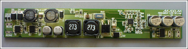
The LED driver reference design described here addresses this basic design challenge with PWM dimming. This LED driver implements PWM dimming based on supply chopping; it does not cause any supply current overshoot. The design provides up to 90% efficiency while operating from a 24V supply. It allows a unidirectional supply input with an efficient semi-MOSFET bridge rectifier at the input. Figure 1 shows the top view of the design board.
Posted on Tuesday, March 8, 2011 • Category: LED
 This code is for a simple RGB LED controller for 1 RGB LED using a PIC12F675 (or PIC12F629). The pattern is determined by the data in the EEPROM. When the PIC needs a new target for the PWM, it loads it from EEPROM. Pin 4 (GP3) is pulled high because it is used to switch between displays. Please see the source code for more information; the structure and design is commented. The operation of the controller is very simple and so is the wiring.
Posted on Saturday, March 5, 2011 • Category: LED
 The implementation of a RGB LED fader using 555 timer and 4029 digital IC is the objective of this project.
During the operation, the RGB LED is continuously cycled through the colors of the rainbow where the speed at which the colors change is adjustable. The switch between the different colors makes the effect very noticeable while a more relaxed effect happens when the colors fade into each other. These two options can be selected on this device.
The pulse generator based form a standard 555 timer is formed by IC1, C1, R4, R5, and VR1. The frequency of which, and hence the speed of the effect, as adjusted using the pre-set VR1. The pulses are fed into IC2 which is a 4029 binary counter whose outputs continuously count in a binary progression between 1 to 7. The transistors Q1, Q2, and Q3 are being driven by these outputs which in turn control each of the three colors of the RGB LED.
By passing through an RC network, the pulses are shaped before they reach their respective transistors. The fading effect between the colors or abrupt changing is produced by this shaping.
Posted on Thursday, October 21, 2010 • Category: LED
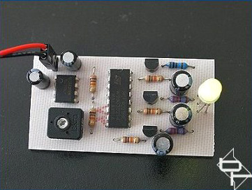
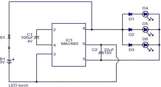 This is a simple LED torch circuit based on IC MAX660 from MAXIM semiconductors. The MAX 660 is a CMOS type monolithic type voltage converter IC. The IC can easily drive three extra bright white LEDs. The LED's are connected in parallel to the output pin 8 of the IC. The circuit has good battery life. The switch S1 can be a push to ON switch.
Posted on Saturday, October 16, 2010 • Category: LED
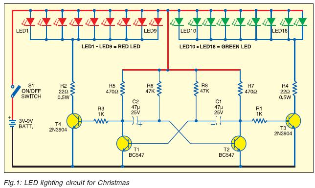 Using light effects for decoration on festive occasions is a normal practice. Designers are coming up with varieties of electronic circuits to fill the imagination of users. Here is an easy-to-assemble circuit for Christmas decoration as shown in Fig.1. It comprises four transistors, eighteen LEDs, a few resistors and two capacitors.
Posted on Saturday, October 16, 2010 • Category: LED
 Here is a low-cost circuit of Christmas star that can be easily constructed even by a novice. The main advantage of this circuit is that it doesn’t require any step-down transformer or ICs. Components like resistors R1 and R2.capacitors C1, C2, and C3, diodes D1 and D2, and zener ZD1 are used to develop a fairly steady 5V DC supply voltage that provides the required current to operate the multivibrator circuit and trigger triac BT136 via LED1.
Posted on Thursday, April 22, 2010 • Category: LED
 For the electric R/C enthusiast, a tachometer can be a very useful piece of equipment. When I first built this tach back in 1995, it was essential, as there were very few off-the-shelf electric R/C power systems that just worked. At that time, you had to experiment with batteries, speed controls or switches, connectors, and wiring, and a tachometer was a tool to help you measure the results.
Posted on Friday, April 16, 2010 • Category: LED
 In many cases can be very handy to be able to convert 1.5V to 5V. Then you can power microcontroller or LED from a single AA or AAA battery. It is simple to do this as there are special IC’s as MAXIM MAX1674 or MAX7176. This is step-up DC-DC converter that can convert voltages from 0.7V to any in range from 2V to 5.5V. MAX1676 have already preset pins for 3.3V and 5V, that makes easer integration in 3.3 and 5V circuits. IC can dissipate up to 444mW.
Bellow is a circuit that converts 1.5V to 5V.
Posted on Friday, April 11, 2008 • Category: LED
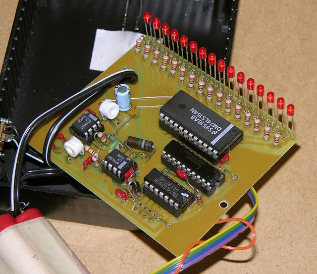
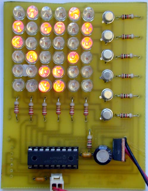 The idea of this project came from my youngest son. He was dreaming of a small tool able to write symbols or pictures on a screen. As a graphic LCD (even bought at Crownhill :) ) was too expensive (or too easy??), the solution adopted was to pilot a matrix of Leds. This way, with only some cheap transistors, common red Leds, and a 16F628 , the dream could become reality.
Posted on Friday, April 11, 2008 • Category: LED
 Two strips of LEDs fading in a complementary manner 9V Battery-operated portable unit. This circuit operates two LED strips in pulsing mode, i.e. one LED strip goes from off state, lights up gradually, then dims gradually, etc. while the other LED strip does the contrary. Each strip can be made up from 2 to 5 LEDs at 9V supply.
Posted on Wednesday, April 9, 2008 • Category: LED
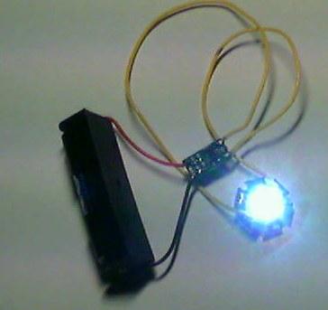
It's a little wisp of a circuit that allows you to drive a blue or white LED from a low voltage. Normally, if you want to light up a blue or white LED you need to provide it with 3 - 3.5 V, like from a 3 V lithium coin cell. But a 1.5 V battery like a AA cell simply will not work. But using the Joule Thief, it works like a charm. Not only does it work with a brand new battery, but it works until the battery is nearly dead-- down to 0.3 V. That's well below the point where your other toys will tell you the battery is dead, so it can steal every last joule of energy from the battery (hence the name). To learn how to make one, watch the video, which is available in a variety of formats.
Circuit-Zone.com © 2007-2026. All Rights Reserved.
|