Circuit-Zone.com - Electronic Projects
Posted on Tuesday, October 2, 2012 • Category: Antennas
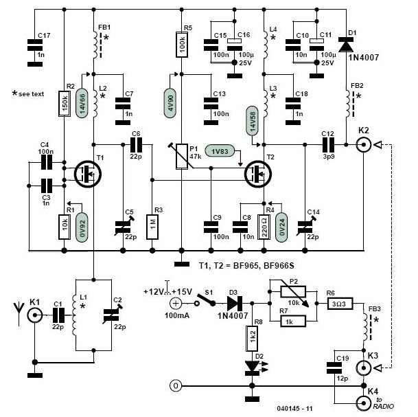
Together with a good directional antenna this high performance two-stage antenna amplifier for the VHF FM broadcast band will enable you to receive distant radio stations. VHF FM Antenna booster will also drastically improve reception of FM signals you’ve come to accept as marginal and noisy in your area. Antenna booster is also great for extending transmission range of low power VHF / FM transmitters.
Posted on Friday, June 15, 2012 • Category: Antennas
 This HD TV UHF wideband amplifier(Ultra High Frequency amplifier) has a total gain of 10 to 15 dB in the 400 – 850 MHz domain frequency so it can be used where the tv signal is weak.
For this UHF antenna tv amplifier to work correctly you need to cut the components pins as short as possible. C1, C2, C6, C7 are SMD type ( surface mounted ). This antenna tv amplifier or uhf wideband amplifier need to be build inside of a metal box and then connected close to the tv antenna.
Posted on Friday, November 4, 2011 • Category: Antennas
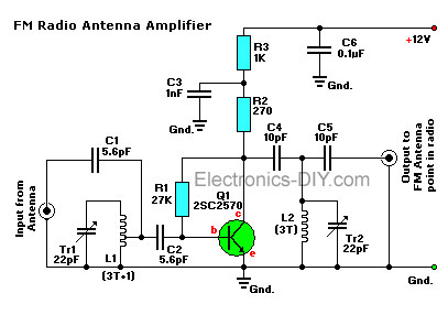 This is a simple active antenna booster. This amplifier will pull in all distant FM stations clearly. The circuits is configured as a common-emitter tuned RF preamplifier wired around VHF/UHF transistor Q1. Input coil L1 consists of four turns of 20SWG enameled copper wire (slightly space wound) over 5mm diameter former. It is tapped at the first turn from ground lead side. Coil L2 is similar to L1, but has only three turns. Pin configuration of transistor 2SC2570 is shown in the fm antenna booster schematic. Adjust input/output trimmers (VC1/VC2) for maximum gain.
Posted on Tuesday, July 19, 2011 • Category: Antennas
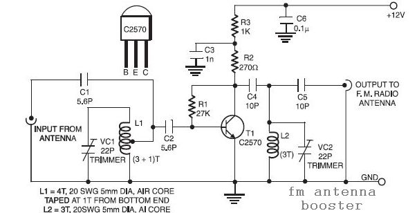 This is a low cost fm antenna booster that can be used to listen to programs from distant FM radio stations clearly. The antenna fm booster circuit comprises a common-emitter tuned RF preamplifier wired around VHF/UHF transistor 2SC2570 (C2570).
Assemble the circuit on a good-quality PCB (preferably, glass-epoxy). Adjust input/output trimmers (VC1/VC2) for maximum gain.
Posted on Saturday, May 21, 2011 • Category: Antennas
 Recently the RASON technical committee was hard at work at the repeater site repairing our 2 meter repeater antenna. One of the members commented to me that I should write an article about collinear arrays so that we could all build our own. While it is not always feasible to home-brew a commercial quality antenna designed to take hurricane force winds, it is very feasible to built a collinear antenna for average use. This article describes a collinear antenna made from very inexpensive RG58/U coaxial cable and encased in PVC pipe.
Before we start building we need to cover some ground about the characteristics of coaxial cable. First remember that there is something called the velocity factor for coaxial cable. For RG58/U coax it is typically .66. This means that when we calculate the length of ½ wavelength in free space we need to adjust its size by multiplying it by the velocity factory. Simply put, RF slows down by the velocity factor when traveling through coaxial cable. All that aside now, lets calculate the ½ wavelength of RG58/U coaxial cable with a frequency of 444 Megahertz.
Posted on Wednesday, December 29, 2010 • Category: Antennas
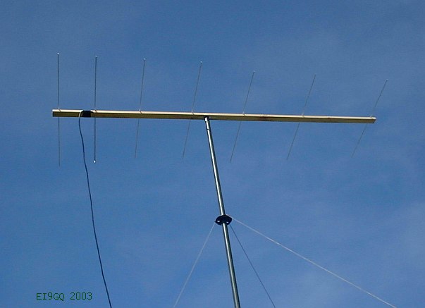 This simple 7 element Yagi is ideal for portable operation. The elements can be removed and replaced in a few minutes. The 2.42 Metre boom will fit inside my car. All of the elements are made from 6mm solid aluminum rod. The boom is made from 50x25mm (2x1 in) timber. The driven element is a half wavelength dipole. Unlike the more common type of folded dipole, this dipole is folded on one side but not on the other. For want of a better name, lets call it a 'half folded dipole'. The co-ax cable braid is connected to the centre of the dipole. The co-ax centre conductor is connected to the folded dipole section (see diagram above).
Posted on Monday, November 15, 2010 • Category: Antennas
 This VHF amplifier working on Band 2 Radio Spectrum tuning approximately 88 - 108 Mhz
The Preamplifier circuit uses two 2N3819 FET's in cascade configuration. The lower FET operates in common source mode, while the upper FET, operates in common gate, realizing full high frequency gain. The bottom FET is tunable allowing a peak for a particular station.
Posted on Saturday, October 9, 2010 • Category: Antennas
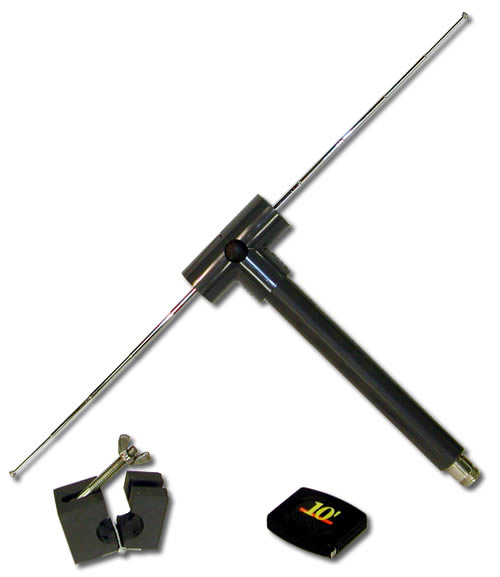
 If you have a shortwave or high-frequency receiver or scanner that is struggling to capture signals with a short, whip antenna, and you'd like the kind of performance that a 60-foot 'longwire' antenna can provide but lack the space to put one up, consider building the AA-7 HF/VHF/UHF Active Antenna described in this article. The AA-7 is a relatively simple antenna that is designed to amplify signals from 3 to 3000 MegaHertz, including three recognized ranges: 3-30Mhz high-frequency (HF) signals; 3-300Mhz very-high frequency (VHF) signals; 300-3000MHz ultra-high (UHF) frequency signals. Those bands are typically occupied by shortwave, ham, government, and commercial radio signals.
Posted on Saturday, October 9, 2010 • Category: Antennas
 An antenna with an integrated RF pre - amplifier
Posted on Thursday, October 7, 2010 • Category: Antennas
Posted on Thursday, October 7, 2010 • Category: Antennas
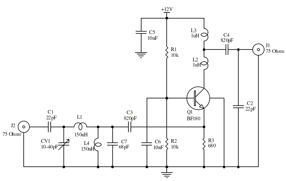 This is an UHF band TV antenna preamplifier circuit With 15dB gain to build easily. It is formed based on BF180 UHF Transistor. The first stage is an band pass filter constructed by the C1, CV1, L1, L4, C7 and C3, the second stage is a base-common voltage amplifier with low input impedance to match. Build the L1 ~ L4 as air core coil to obtain high Q-Factor. After assembling, pack it into a proper metallic box and connect the ground of the circuit to the box to reduce noise effect.
Posted on Saturday, June 5, 2010 • Category: Antennas
 To improve signal transmission or reception in specific directions, basic elements, either vertical or horizontal, can be combined to form arrays. The most common form is the Yagi-Uda parasitic array commonly referred to as a Yagi array or beam.
It consists of a driven element which is either a simple or folded dipole and a series of parasitic elements arranged in a plane. The elements are called parasitic because they are not directly driven by the transmitter but rather absorb energy from the radiated element and re-radiate it.
Posted on Saturday, June 5, 2010 • Category: Antennas
 It is very easy to create a simple 1/2 wave dipole, all you need is some lengths of wire such as the core of some mains flex or even a straightened out metal coat hanger, some co-ax cable and a connector for your scanners antenna input (usually BNC or SMA).
Dipole Antenna
The formula to calculate the length of the antenna is 147/frequency in MHz, this give the total length of the dipole in centimeters. For example, to make a 150MHz dipole: 147/150 = 98cm so each element of the dipole should be 49cm
Posted on Saturday, June 5, 2010 • Category: Antennas
 Tuned for 89MHz in the FM broadcast band.
Posted on Thursday, May 20, 2010 • Category: Antennas
 A modified version of the simple dipole is the folded dipole. It has two half-wave conductors joined at the ends and one conductor is split at the half-way point where the feeder is attached.
If the conductor diameters are the same, the feedpoint impedance of the folded dipole will be four times that of a standard dipole, i.e. 300 ohm.
The height above the ground
The height of an antenna above the ground, and the nature of the ground itself, has a considerable effect on the performance of an antenna.and its angle of radiation. See PROPAGATION
A dipole antenna can be arranged to operate on several bands using other methods. One way is to install "traps" in each leg.
Posted on Thursday, May 20, 2010 • Category: Antennas
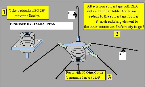 This Antenna is most widely used all over the world. For example, when you see a police car it has a transmitter with Ground Pole Antenna The body of car serves as ground). It accepts load from 50 ohm source and has larger power output than Half-Wave Dipole Antenna.
Posted on Thursday, May 6, 2010 • Category: Antennas
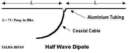 It accepts load from 75 ohm source and has much smaller power output than Ground Pole Antenna. Use this antenna only when you don't have GP Antenna.
Construction: Two aluminum rods ,each of length "L" in meters are joined together through an insulator as shown in fig. From center, 75 ohm cable is feeded just like ordinary TV antenna.
Posted on Sunday, May 2, 2010 • Category: Antennas
 A simple dipole antenna can be used for improved FM broadcast signals. A dipole is basically a length of conductor (wire) split into two portions and signal is taken off at the split. It has a nominal 3 dB gain over an isotropic source and is directional, tending to favor signals broadside to the wire. The dipole is customarily an electrical half wavelength of wire at the frequency of interest, since the impedance under this condition is theoretically 72 ohms resistive and is a good match to a 50-75 ohm source or load generally presented by interfacing equipment such as receivers and transmitters designed to work into this range of impedances.
Posted on Wednesday, April 9, 2008 • Category: Antennas
If you have a shortwave or high-frequency receiver or scanner that is struggling to capture signals with a short, whip antenna, and you'd like the kind of performance that a 60-foot 'longwire' antenna can provide but lack the space to put one up, consider building the AA-7 HF/VHF/UHF Active Antenna described in this article. The AA-7 is a relatively simple antenna that is designed to amplify signals from 3 to 3000 MegaHertz, including three recognized ranges: 3-30Mhz high-frequency (HF) signals; 3-300Mhz very-high frequency (VHF) signals; 300-3000MHz ultra-high (UHF) frequency signals. Those bands are typically occupied by shortwave, ham, government, and commercial radio signals.
Circuit-Zone.com © 2007-2026. All Rights Reserved.
|