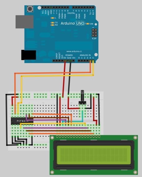
In this tutorial you will learn how to build a simple serial 16x2 LCD display that is controlled via Arduino board by only two wires. The magic behind is done by the PCF8574 chip, an I/O expander that communicates with the micro-controller by using I2C protocol. The PCF8574 is a quick and easy solution to extending and adding output/input ports to Arduino. The chip connects to a standard I2C bus and adds an additional 8 output ports. A total of 8 LCD displays can be connected to the same two wire I2C bus with each board having a different address.
Posted on Wednesday, May 25, 2011 • Category:
Arduino
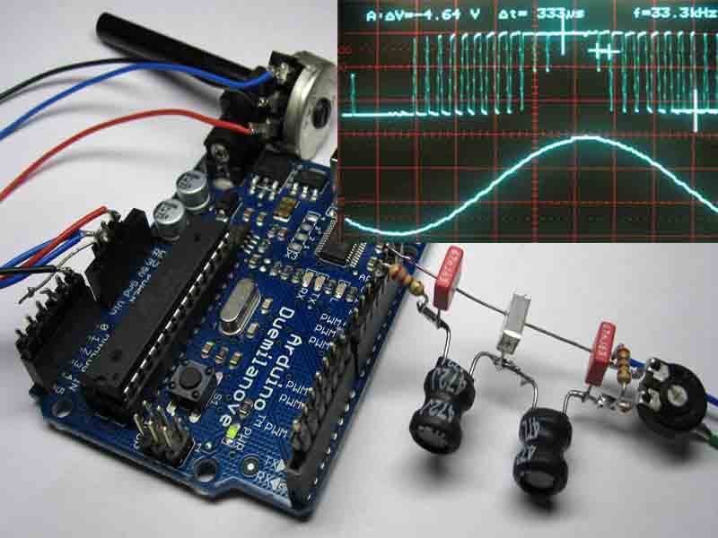
Arduino Sine wave Generator using the direct digital synthesis Method.
Here we describe how to generate sine waves with an Arduino board in a very accurate way. Almost no additional hardware is required. The frequency range reaches form zero to 16 KHz with a resolution of a millionth part of one Hertz! Distortions can be kept less than one percent on frequencies up to 3 KHz. This technique is not only useful for music and sound generation another range of application is test equipment or measurement instrumentation. Also in telecommunication the DDS Method is useful for instance in frequency of phase modulation (FSK PSK).
The DDS Method (digital direct synthesis).
To implement the DDS Method in software we need four components. An accumulator and a tuning word which are in our case just two long integer variables, a sinewave table as a list of numerical values of one sine period stored as constants, a digital analog converter which is provided by the PWM (analogWrite) unit, and a reference clock derived by a internal hardware timer in the atmega. To the accumulator , the tuning word is added, the most significant byte of the accu is taken as address of the sinetable where the value is fetched and outputted as analog value bye the PWM unit. The whole process is cycle timed by an interrupt process which acts as the reference clock. Further details of the DDS Method are described in web of course.
Posted on Wednesday, May 25, 2011 • Category:
Arduino
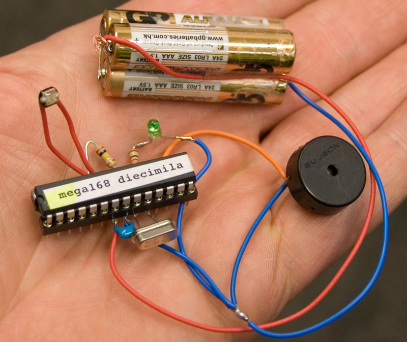
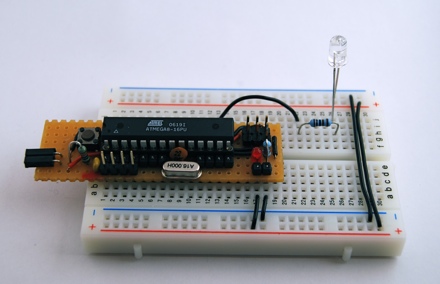
This example shows how to make use of the Watchdog and Sleep functions provided by the ATMEGA168 chip (decimila). These functions are useful if you want to build low power consuming devices operated by battery or solar power.
The reduced power consumption is achieved by through a intermittent operation of the system .In case of Arduino your main loop will be executed once before the system is put into the sleep mode. After a few seconds t the watchdog wakes the system up and the main loop is executed again. The ratio between main loop execution time and watchdog time determines the amount of power that will be saved.
When we assume that the time to measure a sensor and making some decisions will take 10 millisecond and the watchdog is set to 8 seconds the on/off ratio is 800 which extends the battery live time by this factor.
Posted on Tuesday, May 10, 2011 • Category:
Arduino
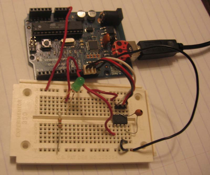
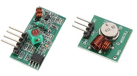
Randall converted an Arduino into AVR chip programming hardware for use with AVRDude. The project programs AVR tiny13 and other tiny AVR chips using an Arduino. He provides code and instructions to implement the Atmel AVR910 In System Programming protocol. I ported the Atmel AVR910 In System Programmer protocol to the Arduino. Now I can write programs to my ATtiny2313 and tiny13 chips. The Arduino sketch is available for download here. It works with the AVRDude programming software. This article will show how to use the Arduino to upload a program to the tiny13. The first step is to download the zip, extract the .pde file, then load it into the Arduino IDE, and write it to the Arduino. Next we can hook up the tiny13 chip.
Posted on Saturday, February 12, 2011 • Category:
Arduino
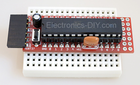
This Arduino can be used for old school prototyping as well. Just use it as a standard ATmega8 and program it with the ISP connector. And it is one of the cheapest Arduino boards, that you can get. Arduino is a great prototyping platform and most of you probably know already about it. If not, check out the Arduino pages and the Arduino playground and dive into it.
Circuit-Zone.com © 2007-2026. All Rights Reserved.