Circuit-Zone.com - Electronic Projects
Posted on Wednesday, May 15, 2013 • Category: FM Radio / Receivers
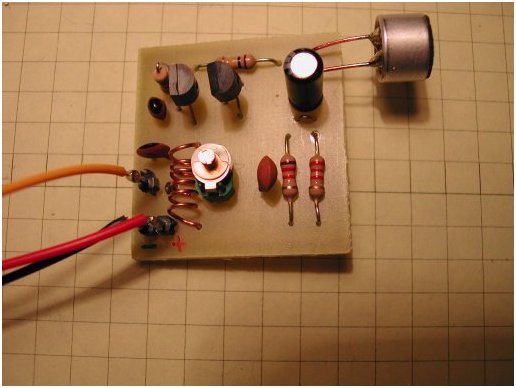
Here's a portable FM broadcast radio receiver for reception of FM broadcast band based around FET transistor. The topology is a classic grounded-gate FET VHF Hartley oscillator. The drain resonator inductance is centre-tapped with feedback to the source through a small capacitance. By tapping down towards the cold-end of the coil the feedback isn't as critical as your usual source-drain capacitor feedback and it tends to be far less difficult to get to work across a broad range of frequencies. The RFC to an RC source circuit to implement self-quenching is very traditional for super-regenerative detectors. The quench gets frequency-modulated somewhat by the drain current, so it varies with signal strength and the recovered modulation, this is typical for self-quenched circuits.
Posted on Saturday, May 11, 2013 • Category: FM Transmitters
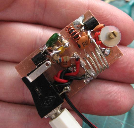
 This article shows you how to build a very simple FM transmitter from thirteen components, a Printed Circuit Board (PCB) and a 9v battery.
This project was designed to be mounted on a PCB, however you don’t have to. You could construct the project on Vero board (strip board) or any other 0.1” pitch style of project board. If you just want to experiment with this circuit, you don’t even need a board; you can just solder the component s together and let the completed project just rest on the work top. No matter which style you choose, try to keep all component leads nice and short.
You could also make the PCB much smaller than the one shown here which is approx. 3 cm square. This is a good size to keep the unit small but nicer to work on for beginners. If you wanted to make one really small, you could use all SMT parts.
Posted on Thursday, May 9, 2013 • Category: Sensors
 Park Assist circuit was designed as an aid in parking the car near the garage wall when backing up. LED D7 illuminates when bumper-wall distance is about 20 cm., D7+D6 illuminate at about 10 cm. and D7+D6+D5 at about 6 cm. In this manner you are alerted when approaching too close to the wall. All distances mentioned before can vary, depending on infra-red transmitting and receiving LEDs used and are mostly affected by the color of the reflecting surface. Black surfaces lower greatly the device sensitivity. Obviously, you can use this circuit in other applications like liquids level detection, proximity devices etc.
Posted on Monday, May 6, 2013 • Category: Test and Measurement
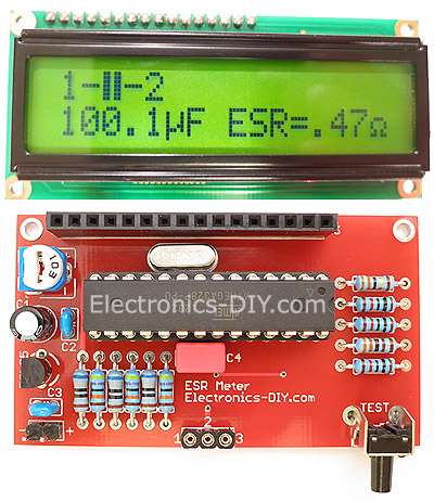 ESR Meter is an irreplaceable tool for troubleshooting and repairing electronic equipment by determining performance and health of electrolytic capacitors. Unlike other ESR Meters that only measure ESR value this one measures capacitor's ESR value as well as its capacitance all at the same time. Additionally, ESR Meter also tests and identifies PINs of all transistors such as Bipolar (NPN, PNP), FETs, MOSFETs (N-Channel, P-Channel, enhancement-mode and depletion-mode MOSFETs), Thyristors, SCRs and Triacs. Tests and identifies PINs and voltage of diodes, dual diodes, varicap diodes (and their capacity), zener diodes (test voltage up to 5V) and LEDs. It measures resistance of resistors, power resistors, coils starting from just 0.1Ω up to 20MΩ.
Posted on Thursday, May 2, 2013 • Category: Remote Control
 If you want control the DVD or TV/AV system that located in your living room via the remote control when you sleeping in your Bedroom. this IR extender will achieve this for you. Basically, it works as a repeater that moves the IR signal to a different location. This is an improved IR remote control extender circuit. It has high noise immunity, is resistant to ambient and reflected light and has an increased range from remote control to the extender circuit of about 7 meters. It should work with any domestic apparatus that use 36-38kHz for the IR carrier frequency.
Posted on Friday, April 26, 2013 • Category: Power Supplies
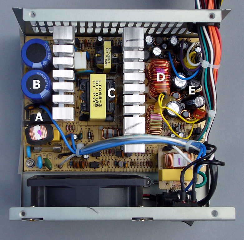 Modern power supplies are known as "switching regulator power supplies."
In most switching supplies, the 110 volt AC input is first rectified by
two diodes and filtered by a pair of capacitors. This creates two high-
voltage sources; one positive and the other negative.
A pair of transistors is then used to switch these high voltage supplies
across the primary winding of a transformer. This switching action is
very fast. A typical switching speed is around 40,000 cycles per second
or 40KHz. An integrated circuit is commonly used to control the
transistors. This IC not only controls the speed at which the
transistors are switched, but also controls the amount of time that each
transistor is energized. The output voltage of the power supply is
determined by the "on" time of the transistors. If the transistors are
keep on for a longer period of time, the output voltage of the supply
will rise, while shorter times lower the output voltage. This is known
as "pulse-width modulation."
Posted on Sunday, April 21, 2013 • Category: Motor Controllers
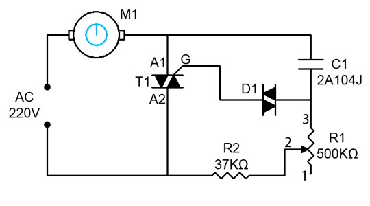 This triac based AC motor speed controller circuit is designed for controlling the speed of AC motors like drill machines, fans, vacuums, etc. The speed of the motor can be controlled by changing the setting of P1 potentiometer. The setting of P1 determines the phase of the trigger pulse that fires the triac. The circuit incorporates a self-stabilizing technique that maintains the speed of the motor even when it is loaded.
Posted on Tuesday, April 16, 2013 • Category: FM Transmitters
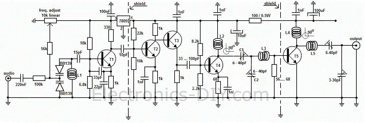 Long range, very stable, harmonic free, FM transmitter circuit which can be used for FM frequencies between 88 and 108 MHz. With good antenna transmitter can cover 5km range. It has a very stable oscillator because it uses LM7809 voltage regulator which is a 9V stabilized power supply for T1 transistor. Frequency adjustment is achieved by using the 10K linear potentiometer. The output power of this long range RF transmitter is around 1W but can be higher if you use transistors like KT920A, BLX65, BLY81, 2N3553, 2SC1970 or 2SC1971.
Posted on Friday, April 12, 2013 • Category: FM Transmitters
 Building two stage 40 Watt FM Transmitter Amplifier. RF input power should be between 0.5 and 1 watt. Amplifier is powered by 28V power supply. The diagram shows a 2N3375 driving a 2N5643 but there are many other transistors that will work. I used these two transistors just because they were cheap at the time. If any of the variable capacitors are at full capacitance you can pad them out with a fixed ceramic capacitor of suitable value. Extra capacitance also might be needed on the base of the transistors (i had to add 3 100pF capacitors on the base of the 2N5643). The transistors are bolted to a piece of right angle aluminum which is fixed to the metal chassis to dissipate heat effectively.
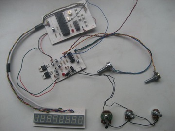
Posted on Thursday, April 4, 2013 • Category: Frequency Wave Generators
Presented here is XR2206 function generator with multiple waveform selection and a frequency readout display. The diagram on the right shows the internal workings of the XR2206 in the form of a block diagram. Essentially the chip contains A VCO (voltage controller oscillator), wave shaper and buffer. The XR2206 frequency generator diagram frequency of the VCO is set with a capacitor and a resistor. The capacitor sets the frequency range whilst a variable resistor can be used to vary the frequency in the set range. The frequency is defined by ƒ = 1/(RC). For a starting point for the design of the frequency generator I used the test circuit from the XR2206 datasheet. I built this on bread board and experimented with the timing resistor and capacitor and managed to get the frequency up to 4MHz.
Circuit-Zone.com © 2007-2026. All Rights Reserved.
|
|
|