Circuit-Zone.com - Electronic Projects
Posted on Tuesday, June 2, 2020 • Category: FM Transmitters
This is a classic low-cost stereo FM transmitter that can send your signal to a FM receiver within 500 meter range. This transmitter uses the famous BA1404 all-in-one chip and operates from 5v power supply. Stereo channel separation is excellent. You can even use this as a front-end stereo RF signal generator for a large FM transmitter setup; by adding step-by-step RF amplifier. A few inch long copper wire can be soldered at the PCB to use as an antenna. The gang-condenser can be used to adjust frequency output. You can use this with your iPod or other audio source, inside your home or car on in an outdoor garden party or wherever you use.
Posted on Monday, May 4, 2020 • Category: Power Supplies
 The LM350 is a tried and true 3A adjustable voltage regulator. It accepts an input voltage up to 35V and can deliver an output voltage between 1.25 and 33V. It is rugged beyond belief. Where fairly beefy step-down converters go up in smoke, the LM350 just takes a nap. And a nap is infinitely better than a plume of smoke. LM350 can also be used to limit current though that requires a separate LM350/LM317 in series with our voltage regulator.
Posted on Tuesday, April 14, 2020 • Category: FM Transmitters
 This is 1 Watt FM amplifier with a good design that can be used to amplify RF signal of low power FM Transmitters in the 88 – 108 MHz band. It is very sensitive if you use good RF power amplifier transistors, trimmers and coils. It has a power amplification factor of 9 to 12 dB (9 to 15 times). At an input power of 0.1W the output will be 1W. You must choose T1 depending on applied voltage. If you have a 12V power supply then use transistors like: 2N4427, KT920A, KT934A, KT904, BLX65, 2SC1970, BLY87. At 18 to 24V power supply you must use transistors like: 2N3866, 2N3553, KT922A, BLY91, BLX92A. You may use 2N2219 at 12V but you will get maximum output power of 0.4W.
Posted on Monday, March 23, 2020 • Category: Amplifiers
 This is 2x30W audio amplifier based on TDA2050 and LM1875. Amplifier PCB is suitable for both TDA2050 and LM1875 chips. Amplifier has all the necessary circuitry on board – power supply, speaker protection, delayed turn-on and fast turn-off. This is achieved using the convenient uPC1237 IC. TDA2050 and LM1875 are pin to pin compatible, the differences in their schematics are the values of a couple resistors and one capacitor. All this allows to make an universal circuit board, suitable for any of these two ICs.
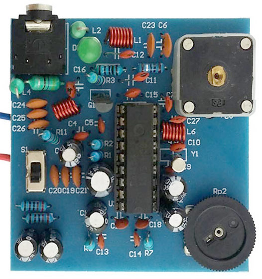
Posted on Monday, March 2, 2020 • Category: FM Transmitters
 RF projects are always special and I am confident that almost every engineer or enthusiast want to try building a RF project. Because of this we have put together a guide for building a super cool Walkie Talkie project. Walkie Talkie is a half duplex wireless communication device that is capable of establishing communication within short range. Half Duplex means only one user can speak or send his message at a time and communication cannot happen simultaneously. These devices are widely used by Security Personal, Industrial workers and so on. Of course it can make a great toy as well. This guide explains about a Walkie Talkie circuit that allows user to establish communication with another identical device within a range of 30m.
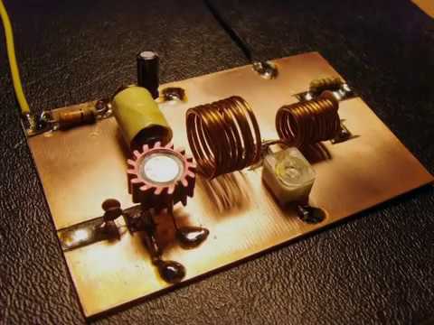
Posted on Tuesday, February 11, 2020 • Category: FM Transmitters
 This is a good quality FM transmitter with 5km range and stable frequency brought by the modified oscillator, which is actually two oscillators built around Q2 and Q3 working at around 50MHz in anti-phase. The output is taken at the two collectors, where the frequencies of the two oscillators combine to form FM signal. This will provide a greater stability than normal single ended oscillators.
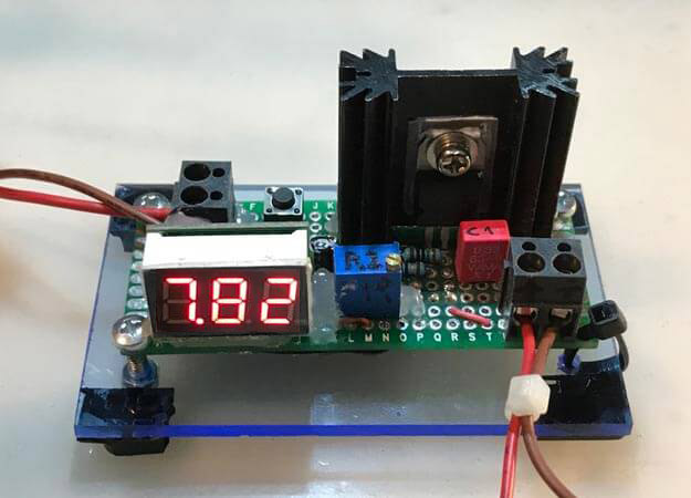
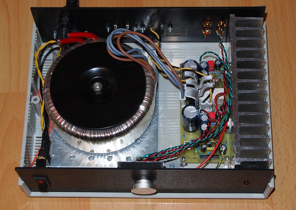
Posted on Sunday, February 2, 2020 • Category: FM Transmitters
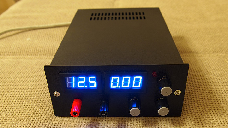 Every laboratory needs a few critical devices, the most important of which is a power supply for powering the projects. But as demand grows and the projects get bigger a professional and adjustable power supply becomes a necessity. Here is an adjustable 50V/5A power supply with a variable output from 0V to 50V and adjustable current limiting from 0A to 5A. Most simple power supplies cant get the output to come down to exactly 0V or 0A. But in this circuit, the differential amplifiers have a negative power supply rail at (-3V), which can pull the output down to exactly zero.
Posted on Wednesday, January 22, 2020 • Category: FM Transmitters
 This tiny FM transmitter can be used for varierty of applications such as monitoring, running your own radio station, etc. It can run on a voltage between 3 and 13 volts, draws 2-3 milliamps and has a theoretical output power of 3 milliamps although you could easily increase that by adding an RF amplifier.
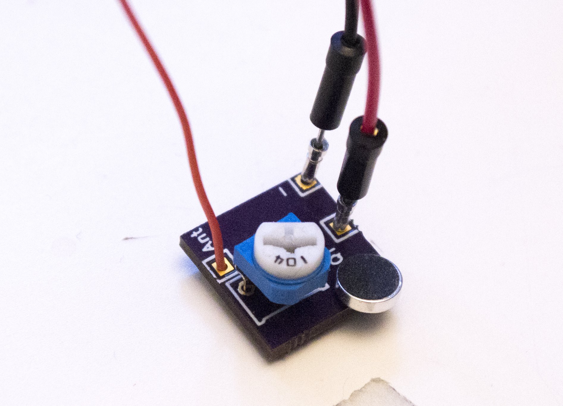
Posted on Tuesday, January 7, 2020 • Category: FM Transmitters
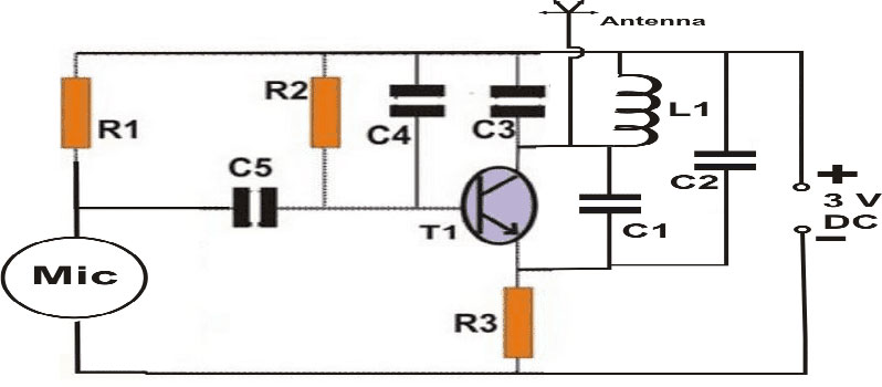 The above wireless FM transmitter circuit is basically a small RF transmitter built around a single transistor. The circuit functions quite like a Colpitts oscillator incorporating a tank circuit for the generation of the required oscillations. The frequency mainly depends on the positioning and the values of the inductor, C1, C2 and C3. The coil turn distance and diameter may be manipulated a little for optimizing best response over the FM receiver. A small antenna in the form of a 3 inches wire may be attached at the shown point for making the “bug” highly responsive and generates distortion free signals.
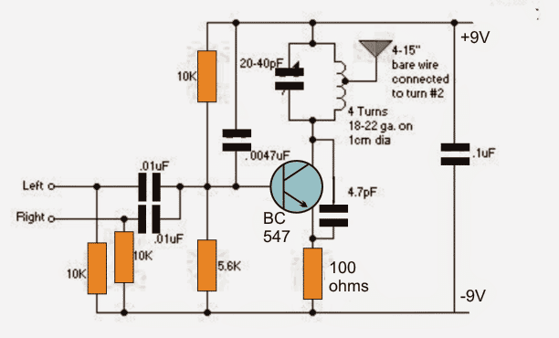
Posted on Tuesday, December 10, 2019 • Category: FM Transmitters
If you want your tiny FM transmitter circuit to transmit music instead of spying or eavesdropping, you would probably find the following design interesting. The proposed FM transmitter will allow combining a stereo input simultaneously from the source so that the info contained inside both the channels get into the air for an optimal reception. The stability of the transmitter is improved by tapping the antenna from one top turn of the coil as shown in the above circuit.
Circuit-Zone.com © 2007-2026. All Rights Reserved.
|
|
|