Circuit-Zone.com - Electronic Projects
Posted on Tuesday, January 3, 2012 • Category: Test and Measurement
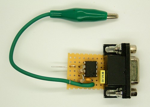
RF laboratory often requires capacitance meter for small capacitors in pF range. Such a device can easily be built by yourself. Here, a measurement converter for PC serial port is presented. The frequency of an oscillator is reduced by the target and measured on a PC. The appropriate conversion then allows the direct display of the capacity. The input uses a short and low capacitance probe tip. The opposite pole is clamped to ground cable with a crocodile.
The NE555 precision timer receives its operating voltage directly from the serial interface and produces a measurement object without C is a square wave with a frequency of 3.5 kHz. The signal is processed via the CTS input of the interface.
Posted on Saturday, December 31, 2011 • Category: Test and Measurement
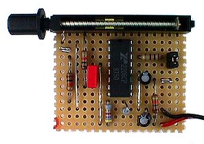 For measurement purposes in the electronics laboratory is needed again and again signals of different frequency and waveforms. A common function generator provides sine, for example, triangular and square waves. The frequency must be adjustable and at least cover the low frequency range.
The low-cost IC XR2206 provides a very simple function generator with only a few external components. XR2206 data sheet provides complete basic circuit for a simple function generator. It requires an operating voltage of 12 V and delivers sine and square wave signals. Instead of the sine wave output is obtained after opening of S1 a triangular output wave. XR2206 IC contains an internal VCO (Voltage Controlled Oscillator, Voltage Controlled Oscillator) with triangular and rectangular output. The capacitor C and the power to determine the frequency at pin 7. With a pot of 2 megohms and a fixed resistor of 1 kOhm variation gives a ratio of 1 to 2000 and may include a range of 10 Hz to 20 kHz sweep.
Posted on Friday, December 30, 2011 • Category: FM Transmitters
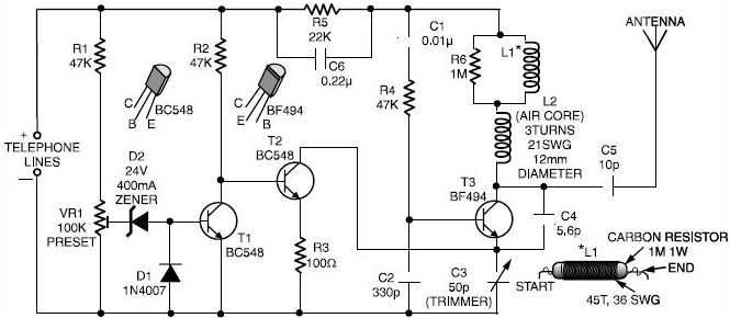 Here is a very simple telephone broadcaster transmitter which can be used to eavesdrop on a telephone conversation. The circuit can also be used as a wireless telephone amplifier.
One important feature of this phone transmitter is that the circuit derives its power directly from the active telephone lines, and thus avoids use of any external battery or other power supplies.
Posted on Wednesday, December 28, 2011 • Category: FM Transmitters
 In this project, you will make a simple 3-stage low-power broadcast-type circuit, using a crystal oscillator integrated circuit and an a collector modulated AM oscillator with amplifier. You can connect the circuit to the an electred microphone or amplified dynamic microphone. Using an electred microphone is shown (in gray) in the diagram below. (no amplified dynamic microphone has a to low output voltage to work. at least 100mv is needed). You could also add a LF preamp stage of one transistor to allow connecting a dynamic microphone directly.
You'll see that you can receive the signal through the air with almost any AM radio receiver. Although the circuits used in radio stations for AM receiving are far more complicated, this nevertheless gives a basic idea of the concept behind a principle transmitter. Plus it is a lot of fun when you actually have it working!
Remember that transmitting on the 10 meter band you'll need a valid radioamateur license!!
A wide range of different circuits have been used for AM, but one of the simplest circuits uses collector modulation applied via (for example) a transformer, while it is perfectly possible to create good designs using solid-state electronics as I applied here (T1 BC557).
The transmitter is build as a Colpitts Oscillator with a BSX20 transistor. HF-output of the oscillator is approx. 50 mW, depending on the supply voltage of 6 to 15 Volts. This is amplified by the BD135 and brings the power up to approx. 1 watt @ 12volts. The transmit frequency is stabilized with the 28Mhz crystal. A slight detuning of approx 1kc is possible when using a 120pF trimmer capacitor for C8. The oscillator signal is taken from the collector of T2 and guided to the input of T3 which output is lead via an L-filter and low-pass PII filter circuit cleaning up the signal pretty good and ensuring spectral purity. The oscillator is keyed by T1 and the morse key (S). By keying the morse-key T1 is not been used for modulation and is biased, hence lets T2 freely oscillate.
Posted on Friday, December 23, 2011 • Category: AC / DC Innveters
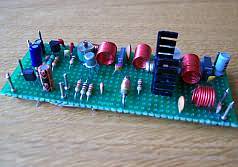
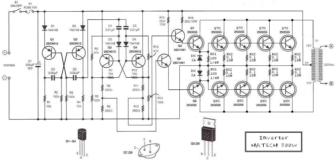 This is a 500W DC-to-AC inverter circuit diagram which produces an AC output at line frequency and voltage. 12VDC to 220V 50Hz inverter circuit will power 220V or 110V appliances from 12V car battery. The circuit is easy to make and is low cost. Use proper transformer. The output (in watts) is up to you by selecting different power rating transformer and power transistor rating. If you load electronic device which require 120V AC, then use transformer with 120V in output.
Posted on Monday, December 19, 2011 • Category: PIC
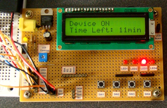 Here is 0 to 99 minutes relay timer using PIC16F628 microcontroller and 16 character LCD display. The microcontroller is PIC16F628A running at 4.0 MHz clock using an external crystal. An HD44780 based 16×2 character LCD is the main display unit of the project where you can watch and set the timer duration using tact switch inputs. There are three tact switches connected to RB0 (Start/Stop), RB1 (Unit), and RB2 (Ten) pins. You can select the timer interval from 0-99 min using Unit and Ten minute switches. The Start/Stop switch is for toggling the timer ON and OFF. When the timer gets ON, a logic high signal appears on the RA3 pin, which can be used to switch on a Relay. The circuit diagram of this project is described below.
Posted on Thursday, December 15, 2011 • Category: FM Transmitters
 This small FM transmitter with a range of about 50 meters designed for hoby. With lots of mini-transmitters then you have a comprehensive, action-packed radio program. Due to the power supply via the USB port of a high frequency stability is achieved. Alternatively, the receiver, a battery 5 to 12 volts to operate.
Posted on Monday, December 12, 2011 • Category: Sensors
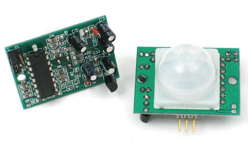 Presented schematic shows how to build simple PIR motion detector sensor. PIR sensors allow you to sense motion, almost always used to detect whether a human has moved in or out of the sensors range. They are small, inexpensive, low-power, easy to use and don't wear out. For that reason they are commonly found in appliances and gadgets used in homes or businesses. They are often referred to as PIR, "Passive Infrared", "Pyroelectric", or "IR motion" sensors.
PIRs are basically made of a pyroelectric sensor (which you can see above as the round metal can with a rectangular crystal in the center), which can detect levels of infrared radiation. Everything emits some low level radiation, and the hotter something is, the more radiation is emitted. The sensor in a motion detector is actually split in two halves. The reason for that is that we are looking to detect motion (change) not average IR levels. The two halves are wired up so that they cancel each other out. If one half sees more or less IR radiation than the other, the output will swing high or low.
Posted on Tuesday, December 6, 2011 • Category: FM Transmitters
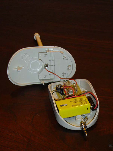 Here are instructions for building your own ipod FM radio transmitter. It works quite easy, there is a power switch on the bottom to turn it on and tune your radio and transmitter to the right frequency. For the antenna you can use a copper wire of 70 cm. The range of this FM transmitter is about 100 to 150 meters (500 feet). With R5 you can adjust the input signal and with C6 you can tune your frequency. Transmitter is supplied by 9V battery.
Posted on Friday, December 2, 2011 • Category: FM Transmitters
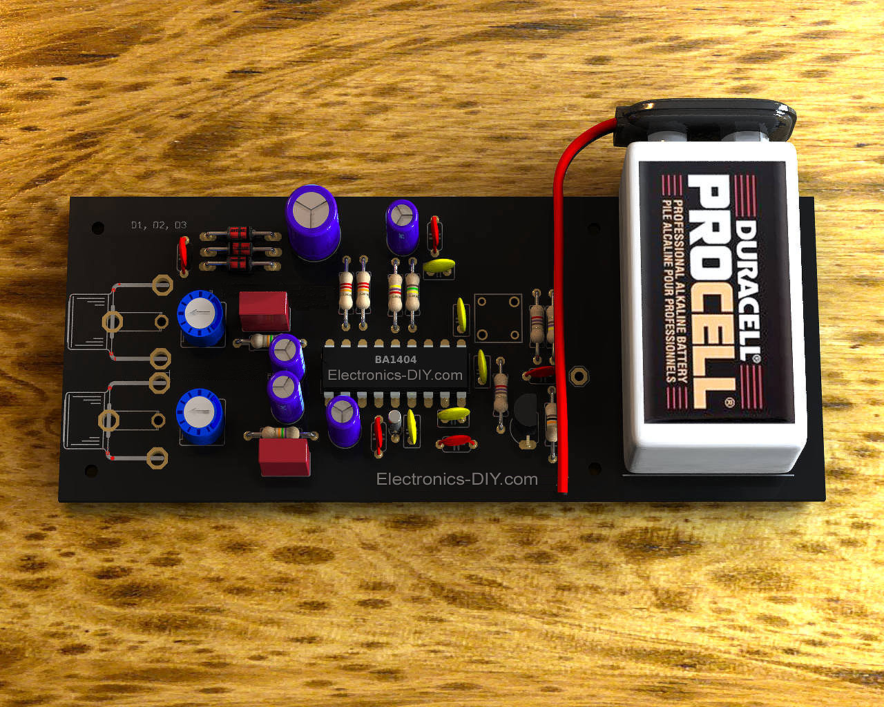
With this Stereo FM Transmitter with BA1404 you will be able to create a mini stereo FM station and broadcast to your entire home, a simple way to have an audio link wireless with ease. With the FM transmitter BA1404 Hifi Stereo you can stream your music from your iPod MP3, satellite receiver, computer, DVD player, Mobile Phone, MP4 player and MP3 and other audio source directly to an FM receiver with crystal clear sound.
Circuit-Zone.com © 2007-2026. All Rights Reserved.
|
|
|