Circuit-Zone.com - Electronic Projects
Posted on Friday, July 8, 2011 • Category: FM Transmitters
The transmitters on my homepage seem to be quite popular, especially those intended for the 88 - 108MHz FM band. I must really confess that I also favor this broadcast band, mainly because it is so easy to find signals on the workshop radio. Everyone has an FM radio, and it is fun to play with. Experimental antennas and the like can all be developed in this band since there are a huge range of "beacons" all transmitting just for my benefit :-). Basic oscillators also are easy to fault-find in this frequency band, and then later modified for other VHF bands.
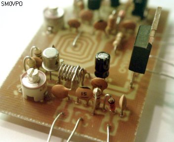
The V5 FM Wireless Microphone is a 10mW transmitter that featured a coil fabricated on the PCB itself. This made the project easy to duplicate and removed "microphony" (the ability of coils to act as a microphone with spring-line reverb). But as several people have already commented, although more stable than most other similar kits and projects, the frequency still does vary with battery voltage. In just one session it can vary by 200kHz when a cheap "Mighty Atom" battery falls to 8 volts.
Posted on Thursday, July 7, 2011 • Category: FM Transmitters
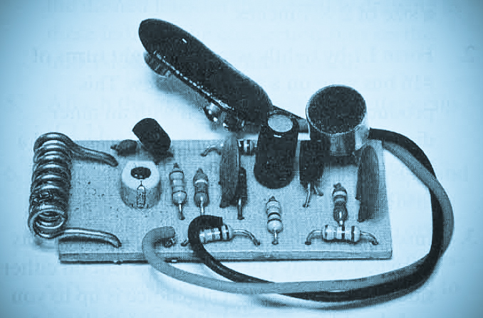 Presented here is a Long Range FM Transmitter. This circuit is a super-sensitive, mini-powered FM transmitter consisting of a RF (radio Frequency) oscillator section interfaced with a high sensitivity, wide pass-band audio amplifier and capacitance mike with a built-in FET (Field Effect Transistor) that modulates the base of the RF oscillator transistor. Transistor Q1 forms a relatively stable RF oscillator whose frequency and is determined by the value of coil L1 and turning capacitor C4.
Posted on Wednesday, July 6, 2011 • Category: TV Transmitters
 Here is a simple TV transmitter. The circuit is simple and really quite crude, but it does include MONO sound. I have not shown the two regulators in the drawing. These are one 12v DC 1A series regulator chip, and one 8v DC 1A series regulator. I fed the 8v regulator from the output of the 12v regulator. The rest of the circuit looks like this. It is a free-running Variable Frequency Oscillator (VFO) using just one coil and one capacitor to determine the frequency. Change this as you will. The basic circuit uses a 150pf from the Base of the RF transistor to ground, so that TR2 operates as a "common-base mode" (grounded base) amplifier. The tuned circuit in the collector and the capacitor from collector to emitter provide tuning and feedback.
Posted on Wednesday, July 6, 2011 • Category: TV Transmitters
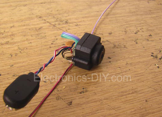 This is a simple video transmitter that can transmit as far as 50 meters. This video transmitter can be used with the camera or other video sources. You can view them on VHF channel analog TV. Supply voltage to the video transmitter can use 9V battery.
Transistor components that are used for a video transmitter is BC548 or you can use another type of transistor BF199. Meanwhile, other passive components used SMD type. For winding coil L1 is 5 Turns 8 mm in diameter and use wire AWG 0.3-0.5 mm.
Posted on Tuesday, July 5, 2011 • Category: AVR
 Here's AVR programmer for programming AVR microcontrollers such as the AT90S1200 via the parallel port. AVR programmer is extremely simple. IC1 provides buffering for the signals that travel from the parallel port to the microcontroller and vice versa. This is essentially everything that can be said about the circuit. The two box headers (K2 and K3) have the ‘standard’ ISP (in system programming) pinout for the AVR controllers. The manufacturer recommends these two pinouts in an attempt to create a kind of standard for the in-circuit programming of AVR microcontrollers. These connections can be found on many development boards for these controllers. The software of AVR programmer carries out the actual programming task.
Posted on Tuesday, July 5, 2011 • Category: Test and Measurement
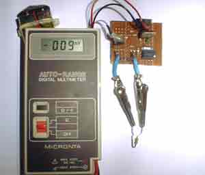 This RF inductance meter measures RF chokes in the 500 nH to 50 uH range. I needed a way to measure hand-wound RF inductors in my second lab, and since I would only be doing this occasionally, I didn't need anything fancy, and since once a friend finishes his AT90S1200-based design, I plan to make one myself, I figured I'd use this for less than a year, so I didn't want to invest a lot of time in making it . I had run across the forerunner of this circuit, one that is more sophisticated in that it has a zero adjustment and range switch, but it was limited to higher inductances. I adapted it to the components I had on hand and changed it so that it would work in the 500 nanohenry to 50 microhenry range.The original circuit was reportedly published a few years ago by the Amrican Radio Relay League, so it is with appreciation of the ARRL that I make this circuit available.
Posted on Monday, July 4, 2011 • Category: Headphone Amplifiers
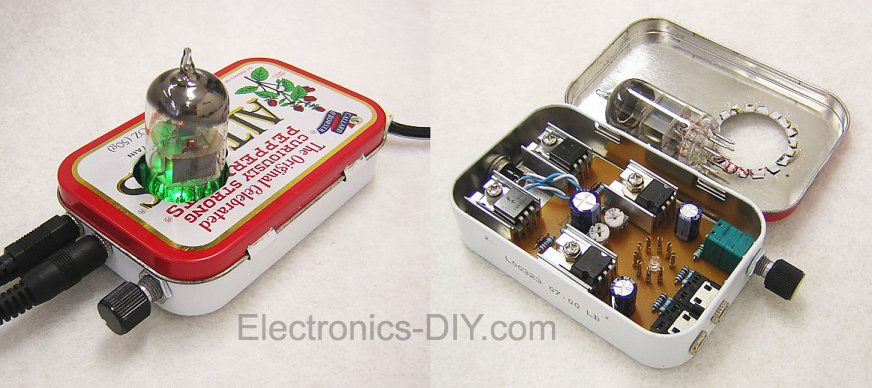 Here's a simple to build hybrid tube headphone amplifier built around 12AU7 / ECC82 vacuum tube. I have always been intrigued by tube amplifiers, but most DIY kits are very expensive and use very high voltage. So I decided to build an amplifier that would be inexpensive and had the least amount of parts necessary to drive a pair of 32 ohm Grado headphones.
Having built several YAHA amps based on the fa-schmidt design, and a Szekeres Mosfet follower I wondered how the two would sound together. So I built the schematic into TINA-TI, a free spice based program to test circuits before the build, and the results were remarkable. Nearly 20dB of gain across 20Hz-100kHz from a 13VDC power supply.
As you see in the schematic and parts list, there are less than 30 discrete components and most DIY'ers will have them as spares from other builds. I chose the 12AU7 / ECC82 vacuum tube because it can be driven with low voltage and the filament voltage is 12.6 volts, so there is no need to regulate the voltage any further. I used 1/4W resistors in the first stage and 2W in the second. The 2W resistors may be overkill but I did not want to change them later. The 20ohm resistor must be a minimum of 5W and do not use wire wound, as the inductive characteristics will distort the response curve.
Posted on Saturday, July 2, 2011 • Category: Test and Measurement
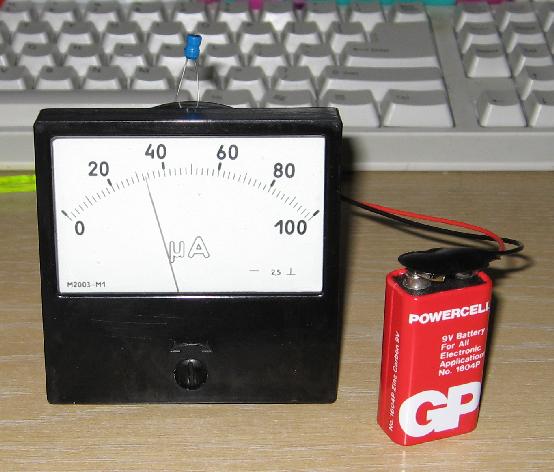 This is inductance meter I built using 74HC14 IC. Initially I used a DMM as the display device, but on a whim I tried hooking up a moving-coil meter. To my surprise, it actually worked just fine, 1K in series was sufficient to allow a useful calibration and didn't overload the drive capabilities of the last gate in the package.
I calibrated my unit for 0-100 uH, as this is the range I am generally most interested in, and it gives direct-readings on the uA scale of the meter. With the values as Dick specified, there is sufficient range to calibrate it from about 25 uH to 250 uH FSD.
Posted on Thursday, June 30, 2011 • Category: FM Transmitters
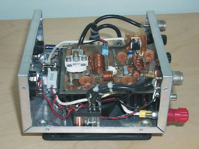 This is a 6m band transmitter RF power amplifier (50 MHz) with 100W output. It used with my FT-736R and drive from 10W for the 6m SSB DX. The Building information comes from Japan CQ Magazine. The Toshiba RF bipolar power transistor is used in it.
If you want to construct this rf amplifier, it's the better way if the double side PCB use for increase the grounding and current transfer. The TX power can be tune to 120W.
Posted on Thursday, June 30, 2011 • Category: Audio DAC
This is USB sound card with PCM2902 chip. For the purpose of testing the D / A converters, I built a simple USB sound card with the circuit PCM2902. The card has analog input and output, an electrical S / PDIF output, galvanically separated input and optical input and output TOSLINK. The heart of USB sound card is PCM2902 it is a circuit connection, which is a complete USB codec. The circuit can handle up to 48kHz sampling frequency. The integrated circuit includes a USB controller for A / D and D / A converter, HID part for 3 buttons, volume control, custom converters and S / PDIF encoder and decoder.
Circuit-Zone.com © 2007-2025. All Rights Reserved.
|
|
|
