HOME   |   STORE   |   SCHEMATICS   |   DOWNLOADS   |   CONTACT  

Circuit-Zone.com - Electronic Projects


Audio Volume Control Attenuator with IR Control
Posted on Saturday, May 28, 2011   •   Category: Amplifiers

Audio Volume Control Attenuator with IR Control

The circuit provides both audio volume and input channel selection. A stepwise volume control is implemented with a set of small relays and resistors. In a high-end audio system, a noticable sound improvement over potentiomeneters can be obtained, also over 'audio grade' potentiometers. Clearly, the IR remote control provides convenience over solutions with stepped attenuator rotary switches. The sealed relays will maintain contact quality over a practically endless lifetime.


75 Meter SSB Transceiver
Posted on Friday, May 27, 2011   •   Category: RF Radio Frequency

75 Meter SSB Transceiver

Here's 75 Meter QRP SSB Transceiver. In general, the transceiver switches the 4-element 1500 ohm xtal BPF ends between the inputs and outputs of the two SA602s to reverse the signal flow for R/T operation. Since no IF amplifier is used in the design, 20 dB of additional receiver gain is produced by the 2N2222 receiver RF amplifier, while automatic gain control (AGC) is produced by the peak DC swing of the LM386 output passed through a rectifier and filtered by a capacitor and fed to the gate of a BS170 enhancement mode FET acting as a variable resistor across the input of the LM386. Both receive and transmit band pass filtering are done by the same half-pi BPF. The diode pair in the mic circuit reduce the "chirp" that occurs during the R/T transition. Additional BS170s could easily be used to mute both the mic and audio instead of the R/T switch directly. These BS170s would be controlled by the +R and +T voltages on their gates while their drains would be tied to 1) the mic circuit between the two coupling capacitors and 2) pin number 1 (audio in) of the LM386 (BS170 sources to ground). Additional power output (perhaps 60 mW) could also be attained by connecting the RF output transistor's collector choke (10 uH) to a 9 V supply instead of the 5 V. Additional biasing current might also be required for this change.


8W PLL Stereo Transmitter with LCD
Posted on Friday, May 27, 2011   •   Category: FM Transmitters

8W PLL Stereo Transmitter with LCD

This is 8W PLL Stereo Transmitter with LCD. It is a stable PLL FM transmitter based on TSA5511 synthesizer. Frequency is performed with three buttons through PIC16F84 microcontroller. Frequency of the transmitter is displayed on 16x1 LCD. Transmitter oscillator is based around BF981, BFR91, BFR96 transistors. 2SC1971 RF power transistor can be replaced with 2N4427 or 2N3553 but they will provide less output power.


LM4780 Gainclone Amplifier
Posted on Thursday, May 26, 2011   •   Category: Amplifiers

LM4780 Gainclone Amplifier

LM4780 gainclone amplifier with a design similar to the National Semiconductor BPA-200 (Bridge/Parallel Amplifier) which uses 4x LM3886 per channel and an input buffer. The total effect is (2x LM3886's paralleled amplifiers) 2x Bridged and should give approx 225 watts into 8 ohm and 335 watts into 4 ohm speakers when used with a sufficient power supply.


LM3875 Gainclone Amplifier
Posted on Thursday, May 26, 2011   •   Category: Amplifiers

LM3875 Gainclone Amplifier

Gainclone amplifiers have very few components and this one is based on the National Semiconductor LM3875 IC. The PCBs and components are very simple and quick to make, only took about 20 mins to assemble both amps and rectifier board. DC offset was about 80mV on one channel and about 40mV on the other. I used the optional Ci capacitor in the national datasheet for the IC which reduced it to between 0-4mV: This is the capacitor I chose, its an Elna Starget (expensive). The case was MUCH more time consuming and difficult to make though. I bought all the aluminium from a scrap metal yard including the heatsink. I got my aluminium panels cut at a sheet metal shop as I cant make straight cuts with a hack saw.


1.5V LED Flasher
Posted on Wednesday, May 25, 2011   •   Category: LED

1.5V LED Flasher

The circuit is a LED flasher to light LED with single 1.5V battery is usually based on a blocking oscillator or a charge-pumped voltage doubler.This is another (but similar to charge pump) way to flash LED with 1.5V battery. The base-R voltage becomes nearly double the Vcc while making oscillation timing of astable multivibrator. LED can be flashed if it is attached aside. Since the LED discharges the C electricity, oscillator timing is shortened.


12V Power Supply - 30A
Posted on Wednesday, May 25, 2011   •   Category: Power Supplies

12V Power Supply - 30A

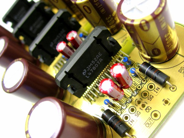
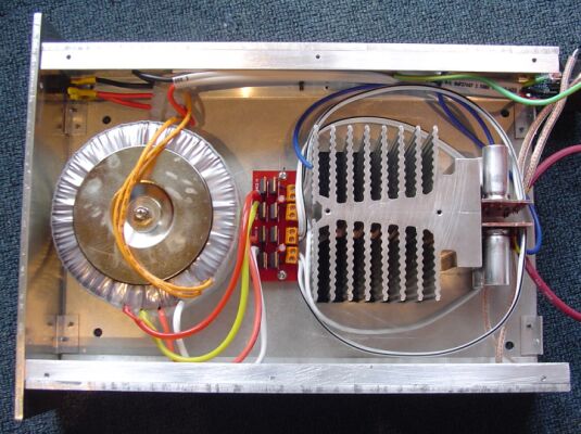
This is high current 12V power supply. Power supply uses LM7812 IC and can deliver up to 30A to the load by the help of the TIP2955 pass transistors. Each transistor can handle up to 5A and six of them result an total output current of 30A. You can increase or reduce the number of TIP2955s to get higher or lower current outputs. In this design the IC delivers about 800mA. A 1 amp fuse is connected after the LM7812 to protect the IC against high current transients. The transistors and the 12V regulator IC both require adequate heatsinking. When the load current is high, the power dissipation of each transistor also increases so excess heat may cause the transistors to fail. Then you will need a very large heatsink or fan cooling. 100Ω resistors are used for stability and prevent current swamping as the tolerances of dc current gain will be different for each transistor. The bridge rectifier diodes must be capable of passing at least 100 amps.


Arduino Sinewave Generator
Posted on Wednesday, May 25, 2011   •   Category: Arduino

Arduino Sinewave Generator

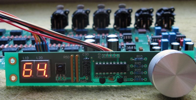
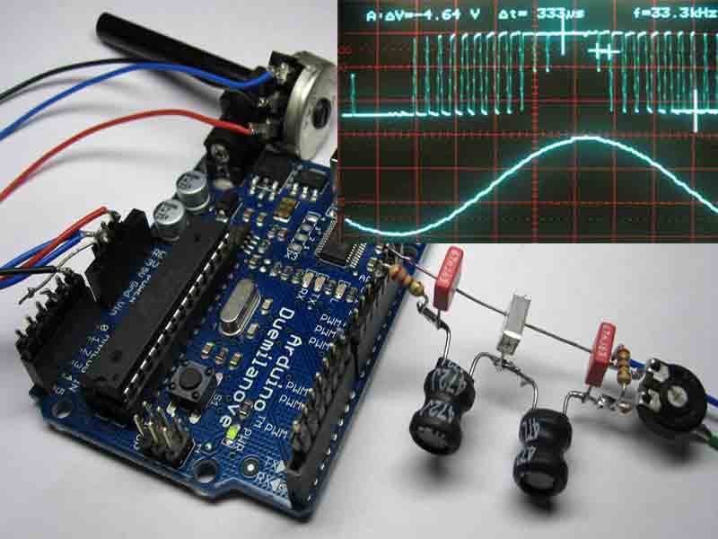
Arduino Sine wave Generator using the direct digital synthesis Method. Here we describe how to generate sine waves with an Arduino board in a very accurate way. Almost no additional hardware is required. The frequency range reaches form zero to 16 KHz with a resolution of a millionth part of one Hertz! Distortions can be kept less than one percent on frequencies up to 3 KHz. This technique is not only useful for music and sound generation another range of application is test equipment or measurement instrumentation. Also in telecommunication the DDS Method is useful for instance in frequency of phase modulation (FSK PSK).

The DDS Method (digital direct synthesis). To implement the DDS Method in software we need four components. An accumulator and a tuning word which are in our case just two long integer variables, a sinewave table as a list of numerical values of one sine period stored as constants, a digital analog converter which is provided by the PWM (analogWrite) unit, and a reference clock derived by a internal hardware timer in the atmega. To the accumulator , the tuning word is added, the most significant byte of the accu is taken as address of the sinetable where the value is fetched and outputted as analog value bye the PWM unit. The whole process is cycle timed by an interrupt process which acts as the reference clock. Further details of the DDS Method are described in web of course.


Arduino Battery Saver - Watchdog and Sleep Functions
Posted on Wednesday, May 25, 2011   •   Category: Arduino

Arduino Battery Saver - Watchdog and Sleep Functions

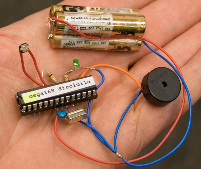
This example shows how to make use of the Watchdog and Sleep functions provided by the ATMEGA168 chip (decimila). These functions are useful if you want to build low power consuming devices operated by battery or solar power.

The reduced power consumption is achieved by through a intermittent operation of the system .In case of Arduino your main loop will be executed once before the system is put into the sleep mode. After a few seconds t the watchdog wakes the system up and the main loop is executed again. The ratio between main loop execution time and watchdog time determines the amount of power that will be saved.

When we assume that the time to measure a sensor and making some decisions will take 10 millisecond and the watchdog is set to 8 seconds the on/off ratio is 800 which extends the battery live time by this factor.


Horsepower Monitor
Posted on Tuesday, May 24, 2011   •   Category: Miscellaneous

Horsepower Monitor

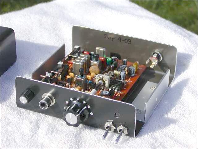
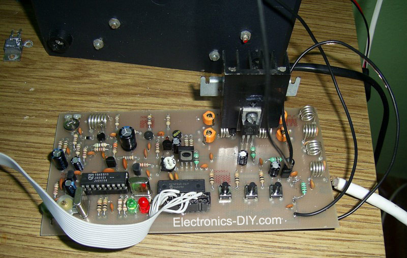
This device is designed to measure the torque in an automobile drive shaft and provide an output to a vehicle data recording system or a portable computer via an RS-232 interface. The received data can then be combined with RPM measurements from the data recording system to calculate horsepower. It consists of the sensor unit, (Figure 1), which attaches to the driveshaft, and the receiver unit, , which provides the serial output signal. The sensor unit is battery powered and communicates with the receiver via a 433 Mhz RF data link.The receiver unit is powered by the vehicle electrical system. Circuit operation is shown in the diagram.


Page 30 of 80:   1   2   3   4   5   6   7   8   9   10   11   12   13   14   15   16   17   18   19   20   21   22   23   24   25   26   27   28   29   30   31   32   33   34   35   36   37   38   39   40   41   42   43   44   45   46   47   48   49   50   51   52   53   54   55   56   57   58   59   60   61   62   63   64   65   66   67   68   69   70   71   72   73   74   75   76   77   78   79   80

Circuit-Zone.com © 2007-2024. All Rights Reserved.

AC / DC Innveters
AM Radio
Amplifiers
Antennas
Arduino
Audio Attenuators
Audio DAC
AVR
Battery Chargers
CNC Milling Devices
Counters / Frequency Meters
Fluorescent Lamps
FM Radio / Receivers
FM Transmitters
Frequency Wave Generators
Headphone Amplifiers
iPOD Hacks
LC Meter
LED
Miscellaneous
Motor Controllers
MP3 Players
Oscillators
Oscilloscopes
PC Circuits
PCB
Phone Circuits
PIC
PLL Circuits
Power Supplies
RC Servo Motors
Remote Control
RF Radio Frequency
Robots
Sensors
Solar Circuits
Stepper Motors
Stereo Encoders
Test and Measurement
Timer Circuits
TV Transmitters
USB Circuts
USB Interface Adapters
USB Soundcards / USB Headphones
Video
Volume Control