Circuit-Zone.com - Electronic Projects
Posted on Wednesday, October 12, 2011 • Category: FM Transmitters
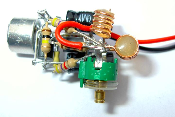
This is a simple design of a small FM Transmitter Bug that's perfect for transmitting and eavesdropping purposes. Due to the high sensitivity, even the ticking of the clock to hear. The range is estimated at anything from 50 meters. With a small piece of wire as an antenna to get at least the whole house. L1 and L2 are two equal air pools. They each consist of 5 turns at a diameter of about 4 mm. The thickness of the wire does not matter, 0.5 mm works perfectly. C4 is the frequency adjustment. Tune an FM radio in an empty area of the FM band and C4 to turn your silence or hear a whistle. From what you can precisely adjust the radio and the transmitter installed in a room somewhere to intercept. Note: Because these transmitter bugs inherently unstable, you better read the short legs of the components keep the circuit mechanically tightly together up. Also placing a 1 nF capacitor (C6) will benefit stability.
R1, R3, R4: 4K7
R2: 100K
R5: 10K
R6: 270 Ohms
C1, C2: 10 uF
C3, C6: 1 nF
C4: 2-18 pF trimmer
C5: 5.6 pF
L1, L2: air puddle windings on May 4 mm in diameter (see text)
T1, T2: 547 BC
Condenser microphone
Original Text:
Ook het plaatsen van een 1 nF condensatortje (C6) over de voedingsaanluitingen komt de werking ten goede. [Origineel TinyCAD ontwerp]
Show alternative translations
Posted on Saturday, October 8, 2011 • Category: Power Supplies
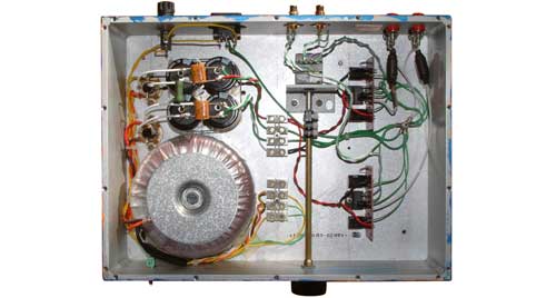
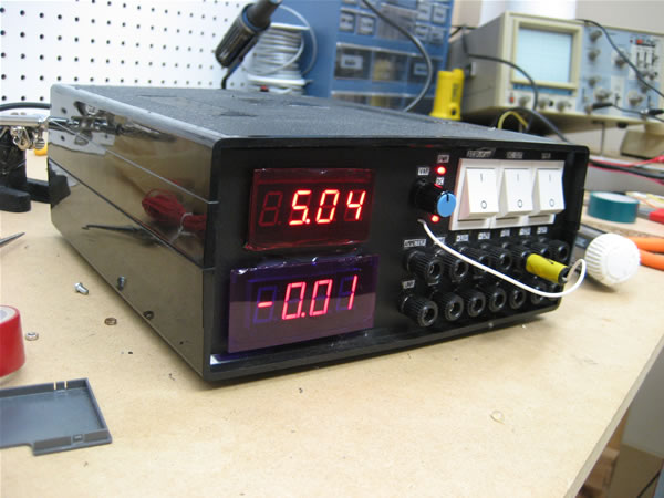 Presented here is a circuit for 30V 10A variable bench power supply that offers variable voltage and current adjustment. Power supply is based around a LM723 voltage regulator chip and has current limiting. I often end up with the power clips shorting out on the bench and with no problems. I have had this circuit in use now for over 20 years and has never let me down and is one of the most handiest gadgets i have built. The 2N3055 transistors are a well proven high current transistor. More 2N3055 transistors can be connected together for more output current. The transistors will need to be mounted on a good size heatsink.
Posted on Friday, September 23, 2011 • Category: FM Transmitters
 The circuit shown here is of a good Stereo FM transmitter that can transmit high quality signals up to a range of 70 feet. The circuit is based on BH1417 PLL stereo transmitter IC from Rhom semiconductors. The IC has separate audio processing sections for the left and right channels, pre emphasis circuit for improving signal to noise ratio, crystal control circuitry for accurate frequency locking, multiplex circuit for making sum ( left plus right) and difference ( left minus right) {see this article for better understanding Stereo decoder circuit} etc. Another important feature of this IC is that the transmission frequency can be set using a 4 channel DIP switch. The IC can be powered from anything between 4 to 6V DC and has an output power around 20mW. At full output power the circuit consumes only 20mA and has a channel separation of 40dB.There are 14 possible preset transmission frequencies, starting from 88.7MHz and incrementing in steps of 0.2MHz that can be selected using the DIP switch. The PLL circuitry of the IC is so precise that there is practically no frequency drift.
Posted on Sunday, September 11, 2011 • Category: Test and Measurement
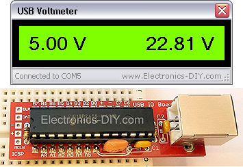 USB Voltmeter is a PC based dual channel voltmeter built around PIC18F2455 / PIC18F2550 microcontroller that measures voltage from 0.00V up to 500.00V with 10mV resolution. USB Voltmeter sends measured data to PC via standard USB connection displaying data on a computer monitor. USB Voltmeter is self-powered drawing very little current from USB port. Voltage readings are displayed via included USB Voltmeter software.
Posted on Thursday, August 25, 2011 • Category: FM Transmitters
 This miniature transmitter is easy to construct and it's transmissions can be picked up on any standard FM receiver. It has a range of up to 1/4 of a mile or more. It is great for room monitoring, baby listening, nature research, etc. L1 is 8 to 10 turns of 22 gauge hookup wire close wound around a non-conductive 1/4 inch diameter form, such as a pencil. C4 is a small, screw-adjustable, trimmer capacitor. Set your FM receiver for a clear, blank space in the lower end of the band. Then, with a non-conductive tool, adjust this capacitor for the clearest reception. A little experimenting and patience may be in order. Most of the parts' values are not critical, so you can try adjusting them to see what happens.
Posted on Monday, August 22, 2011 • Category: Amplifiers
 Several years ago, National Semiconductor came up with some very high performance, easy to use audio power amplifier LM3886 circuits. I needed an extra amp so I can bi-amp some of my homemade electrostatic speakers so I tried the LM3886 chip. LM3886 amplifier was chosen because of ease of use, performance, low distortion and a built-in protection against short circuits and thermal instability. There is not much to remove a power amp, than asking. When driving electrostatic speakers, you can not be much protection.
There are people who have “golden ears” and the feeling, provided that no application note scheme is never good enough for it to “Optimize” to “improvements” to make a claim. The problem is that most of them do not engineers and have no idea what the possible consequences of their “improvements” can be. For example, for a few years if these chips were popular with the audiophile crowd, it was all the rage at minimum power filter caps for “Best Sound” to use. We are talking about 500 uF on each power rail for each chip used LM3886 amplifier. This is clearly insufficient and leads to a distortion in the volume low enough that the power supply sags under load. The problem was that some of the golden ears of the large power supply rejection IC spec saw and thought it meant that the chip could tolerate the 10V power supply ripple. The pendulum has swung the other way, and now many music lovers are sufficient amounts of energy storage in the diet.
Posted on Friday, August 12, 2011 • Category: TV Transmitters
 This TV transmitter transmits audio and video signal from Camcoder Camera, DVD, VHS, Satellite, video game, etc. Playing them in a channel free from the strip of VHF.
These signal can be radiated with a common antenna and captured in an it distances of until about 500 meters that it is the most appropriate for urban areas, reminding that and necessary to be a lot of caution and careful for not interfering in frequencies of other issuing, as well as to emergency services. Depending on the local conditions (existence or not of obstacles). Fed with tensions from 12 to 15 Volts, the circuit has excellent I carry out so much in the emission of monochrome signal, as in colors. An important point of this project ‚the easiness with that he can be set up and adjusted, since only two coils are used. Ideal to be used with surveillance cameras turning the without thread.
As it Works the tv video and audio transmitter with lm1889n
The heart of this circuit transmitter ‚is the integrated circuit LM1889N of National Semiconductor, that consists of a Modulator of Video for TV in an involucres of 18 pins DIL.
Posted on Wednesday, August 10, 2011 • Category: Test and Measurement
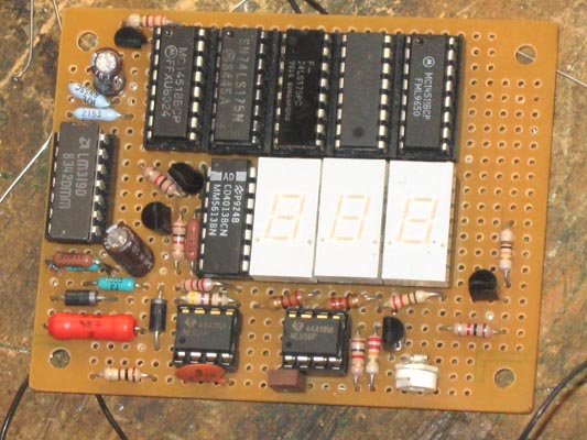
 Even if the digital multimeter have dominated in a lot of applications, in the measurement, exist the need for existence of instruments of clue in various appliances, voltage and current, as in power supply or elsewhere. The circuits that give make this precisely the work, measure the voltage in terminal a circuit and the current that passes in his. The circuit does not present particular difficulties for somebody that has a small experience. The two circuits are the himself, with a small difference only in their input, when they have they measure voltage or current and in connection that concern decimal point [ dp ]. In the department of input IC1 and IC3, exist the CA3161E, that is a A/D Converter for 3-Digit Display. In the drive of Display IC2 and IC4, exist CA3161E, that is a BCD the Seven Segment Decoder/ Driver. As it appear in Fig.1, that concern the voltmeter in input [ + IN ], exist in series a what resistor R1 in combination with the R3 create a voltage divider. On the contrary in the Fig.2 that it concern the ampere meter, this resistor does not exist, because the circuit is connected differently, thus the current pass through the R5, creating a fall of voltage, in her terminal, proportional current that it pass from this.
Posted on Monday, August 8, 2011 • Category: FM Transmitters
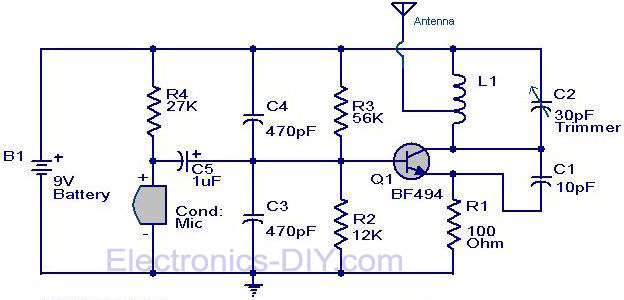 Here is the circuit diagram of the simple FM transmitter using a transistor. Great performance or range is not guaranteed here, because this is an elementary design. General purpose radio frequency transistor BF 494 (Q1) is used here for obtaining FM modulation. A condenser mic is used here to pickup the sound.The condenser mic converts the sound to electrical variations and this variations are fed to the base of Q1 , which performs the amplification as well as modulation.The capacitor C2 and L1 determines the frequency of transmission.The circuit can be powered from a 9V transistor radio battery.
Posted on Saturday, August 6, 2011 • Category: Test and Measurement
I wanted a digital AC voltmeter to measure the output range from 0 to 150VAC with reasonable accuracy. Sure I could buy some premade DVM packages or use a microcontroller with a built-in ADC, but I wanted to make one from scratch myself using readily available parts I had on hand. I aimed for reasonable accuracy so I chose to have a 2 and a half display for the voltage, meaning the meter reads from 000 to 199. Below is the schematic of the AC DVM.
Circuit-Zone.com © 2007-2026. All Rights Reserved.
|