Circuit-Zone.com - Electronic Projects
Posted on Monday, November 28, 2011 • Category: Amplifiers
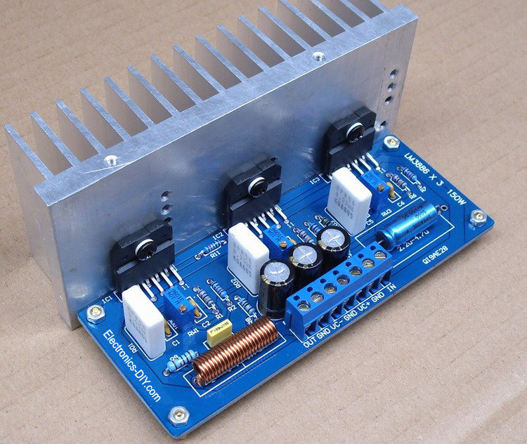
LM3886 power amplifier with 150W audio output power. Three LM3886 amplifiers are bridged together to achieve 150W. Power supply is +/- 30V. LM3886 amplifier maintains an excellent signal-to-noise ratio of greater than 92dB with a typical low noise floor of 2.0µV. It exhibits extremely low THD+N values of 0.03% at the rated output into the rated load over the audio spectrum, and provides excellent linearity with an IMD (SMPTE) typical rating of 0.004%
Posted on Friday, November 18, 2011 • Category: FM Transmitters
 Here's simple FM transmitter circuit using medium power 2N2218 transistor. Micropohone is of electret type that connects to two input terminals and the antenna should be a copper wire from 15 to 40 cm. Below is schematic circuit of the fm transmitter.
Posted on Sunday, November 13, 2011 • Category: AM Radio
 AM radio built around 555 timer chip. The only active device (silicon, germanium, or otherwise) is the LM555. The tuning is accomplished with an inductor and a capacitor, and the LM555 acts as an AM demodulator and class-D power amplifier to drive the speaker. You may be wondering how all this is accomplished with a 555. Here’s how the circuit works: The AM radio signal is tuned by inductor L, which is 300 turns of wire on a 1/2 inch diameter cardboard tube made out of a paper roll, along with the 100pF variable capacitor. One end of the parallel configuration of L and C connects to an antenna (surprisingly long!) and the other end connects to a ground wire which is tied to the AC outlet ground (old books tell you to ground it to a water pipe). So far this is exactly like an AM crystal radio.
The 555 timer is configured as a pulse width modulator in a non-traditional configuration. If I used the standard approach and connected the input to the CV pin, the low impedance of the pin would prevent the circuit from receiving any radio signals. I had to invert the circuit and tie both high impedance analog pins, Threshold and Trigger to the radio signal input. This is the reason why the CMOS version of the 555 timer performs much better than the standard bipolar, which has higher input bias current.
Posted on Friday, November 4, 2011 • Category: Antennas
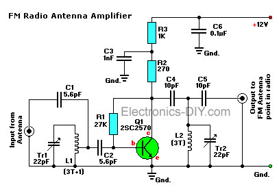 This is a simple active antenna booster. This amplifier will pull in all distant FM stations clearly. The circuits is configured as a common-emitter tuned RF preamplifier wired around VHF/UHF transistor Q1. Input coil L1 consists of four turns of 20SWG enameled copper wire (slightly space wound) over 5mm diameter former. It is tapped at the first turn from ground lead side. Coil L2 is similar to L1, but has only three turns. Pin configuration of transistor 2SC2570 is shown in the fm antenna booster schematic. Adjust input/output trimmers (VC1/VC2) for maximum gain.
Posted on Friday, November 4, 2011 • Category: Amplifiers
 Here's low power stereo amplifier built around TDA2822 chip. Many people may have heard of the TDA2822 before, but for those who haven't, it is a small power amplifier that will drive two channels. It is usually in an 8-pin DIL package, but older versions I have seen are 14-pin or similar (there are datasheets for both variants). For simplicity though, my circuits show schematics for the 8-pin DIL package. The datasheet is here, provided by ST. This article is based along the usage of the TDA2822M variant of the chip series as it is commonly available. The TDA2822 is similar, but has slightly more pins so is less used.
Posted on Friday, October 28, 2011 • Category: FM Transmitters
 Here's 1W RF Amplifier is for boosting small fm transmitters and bugs. It use two Philips 2N4427 and its power is about 1Watt. At the output you can drive any linear with BGY133 or BLY87 and so on. Its power supply has to give 500mA current at 12 Volts. More voltage can boost the distance but the transistors will be burned much earlier than usual.! In any case do not exceed the 15Volts. The Amp offers 15 dB in the area of 80Mhz to 110 Mhz. L4, L5, and L6 are 5mm diameter air coils, 8 turns, with wire 1mm wire diameter.An easy project, with great results.
Posted on Thursday, October 27, 2011 • Category: Amplifiers
 I built my first power amplifier when I was still in secondary school. The circuit was made of transistors, didn't provide much power and had an ugly PCB.
Around the same time I got access to a datasheet of TDA1524, a tone/volume control circuit, and I decided to use it to build a pre-amplifier, to improve the quality of the sound coming out of the amplifer. Both circuits worked well for almost a decade but the old amplifier was never up to my expectations.
In 2006 I decided that it was time to build a real power amplifier, this time based on an integrated circuit to reduce the number of external components and cost.
Posted on Sunday, October 23, 2011 • Category: FM Transmitters
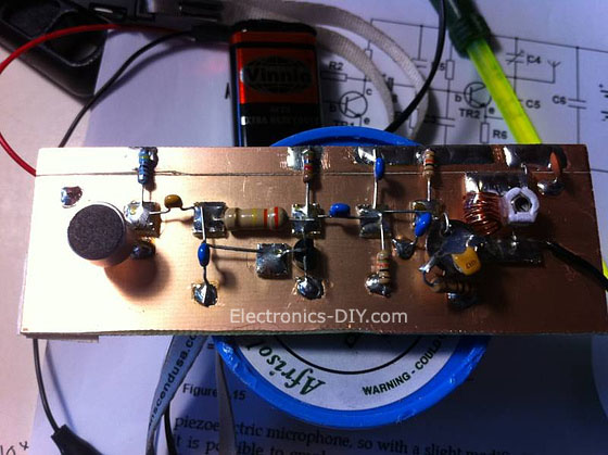
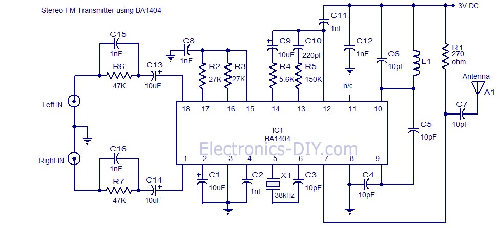 A high quality stereo FM transmitter circuit is shown here. The circuit is based on the IC BA1404 from ROHM Semiconductors. BA1404 is a monolithic FM stereo modulator that has built in stereo modulator, FM modulator and RF amplifier. The FM modulator can be operated from 76 to 108MHz and power supply for the circuit can be anything between 1.25 to 3 volts.
In the circuit R7, C16, C14 and R6, C15, C13 forms the pre-emphasis network for the right and left channels respectively. This is done for matching the frequency response of the FM transmitter with the FM receiver. Inductor L1 and capacitor C5 is used to set the oscillator frequency. Network C9,C10, R4,R5 improves the channel separation. 38kHz crystal X1 is connected between pins 5 and 6 of the IC. Composite stereo signal is created by the stereo modulator circuit using the 38kHz quartz controlled frequency.
Posted on Sunday, October 23, 2011 • Category: Power Supplies
 This is an add-on over voltage protection circuit for LM317 voltage regulator. It is a voltage regulator that allows a 6V portable supply to be derived from the 12V car battery. You can add a 6.2V zener diode and a LED to warn you when the input supply is overvoltage. If you could find a relay that would operate from 6.2V right up to 12v that you could connect in such a way that if over voltage occurred, then the relay would automatically switch off the output preventing damage to any connected equipment.
Such a relay would be quite difficult to find, so I designed this, it is a simple two transistor circuit which will switch off the output should the voltage raise above 6.2v this can be changed by selecting a different value of zener diode.
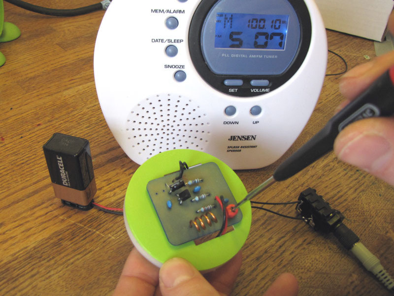
Posted on Tuesday, October 18, 2011 • Category: FM Transmitters
This simple FM Transmitter takes audio input through a 1/4" phono jack and, constructed as shown, without the optional antenna connections, will broadcast an FM radio signal about 30 feet. This is the standard model of simplest FM transmitters includes a trim capacitor to adjust the transmitting frequency. It can be powered by a 9V battery and uses a hand-turned copper coil. The circuit is extraordinarily simple and could be built on perfboard or on a panel almost as easily.
Circuit-Zone.com © 2007-2026. All Rights Reserved.
|