Posted on Thursday, May 5, 2011 • Category: Stepper Motors
Stepper motors are everywhere in electronics these days. There are two main types of stepper motors:
1. Bipolar motors. These have two coils and are controlled by changing the direction of the current flow through the coils in the proper sequence. These motors have only four wires and cannot be connected to this kit. See our Kit 1406 for a Bipolar Stepper driver Kit.
2. Unipolar motors. These have two center-tapped coils which are treated as four coils. These motors can have five, six or eight wires. Five-wire motors have the two center-taps commoned internally and brought out as one wire (Fig 1). Six-wire motors bring out each center-tap separately. The two center-taps need to be commoned externally (Fig 2). Eight-wire motors bring out both ends of each coil. The four “center-taps” are joined externally to form one wire. In each case the center-tap(s) are connected to a positive motor power supply. Unipolar motors may be connect as bipolar ones by not using the ‘+’ wires.
A stepper motor has no brushes or contacts. It is basically a synchronous motor with the magnetic field electronically switched to rotate the armature magnet around.
The Internet is where to get all the explanation about steppers. Just google ‘stepper motor’ and you will find tens of sites. In particular, look for ‘Jones on Stepper motors’ (it comes up top of the list when I did it just now) and read it. If you look at the other references you will find that the circuit in this kit has been around for many years in various forms. The latest publication was in Silicon Chip, 5/2002, and I have based this circuit on it.
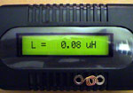
Build Accurate LC Meter and start making your own coils and inductors. This LC Meter allows to measure incredibly small inductances making it perfect tool for making all types of RF coils. LC Meter can measure inductances starting from 10nH - 1000nH, 1uH - 1000uH, 1mH - 100mH and capacitances from 0.1pF up to 900nF. The circuit includes an auto ranging and reset function to make sure the readings are as accurate as possible ... [more]