Circuit-Zone.com - Electronic Projects
Posted on Saturday, July 9, 2011 • Category: Phone Circuits
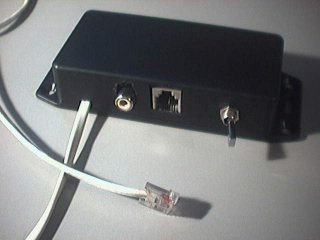
I needed a way to extract audio from a phone line for my DTMF decoder. I found a site full of examples on how to do it, and I built an interface that suited my needs:
RCA output, with a signal strong enough to be fed directly to an audio amplifier or line-in.
The interface can stay connected on the line at anytime (no problems with the ring signal), and does not take of the hook.
The interface must provide isolation from the line.
I discovered that it can also be used to inject audio in the line.
Posted on Thursday, May 12, 2011 • Category: Phone Circuits
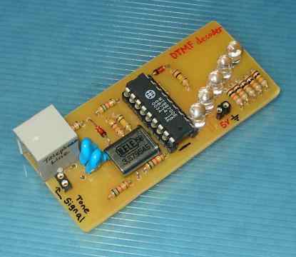 This circuit detects the dial tone from a telephone line and decodes the keypad pressed on the remote telephone. The dial tone we heard when we pick up the phone set is call Dual Tone Multi-Frequency, DTMF in short. The name was given because the tone that we heard over the phone is actually make up of two distinct frequency tone, hence the name dual tone. The DTMF tone is a form of one way communication between the dialer and the telephone exchange.
A complete communication consist of the tone generator and the tone decoder. In this article, we are use the IC MT8870DE, the main component to decode the input dial tone to 5 digital output. These digital bits can be interface to a computer or microcontroller for further application eg. remote control, phone line transfer operation, LEDs, etc...
Posted on Thursday, April 28, 2011 • Category: Phone Circuits
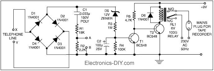 This circuit enables automatic switching-on of the tape recorder when the handset is lifted. The tape recorder gets switched off when the handset is replaced. The signals are suitably attenuated to a level at which they can be recorded using the ‘MICIN’ socket of the tape recorder.
Points X and Y in the circuit are connected to the telephone lines. Resistors R1 and R2 act as a voltage divider. The voltage appearing across R2 is fed to the ‘MIC-IN’ socket of the tape recorder. The values of R1 and R2 may be changed depending on the input impedance of the tape recorder’s ‘MIC-IN’ terminals. Capacitor C1 is used for blocking the flow of DC.
The second part of the circuit controls relay RL1, which is used to switch on/off the tape recorder. A voltage of 48 volts appears across the telephone lines in on-hook condition. This voltage drops to about 9 volts when the handset is lifted. Diodes D1 through D4 constitute a bridge rectifier/polarity guard. This ensures that transistor T1 gets voltage of proper polarity, irrespective of the polarity of the telephone lines.
Posted on Sunday, January 30, 2011 • Category: Phone Circuits
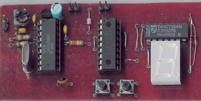 DTMF tone is mainly used in telecommunication technology, such as dialing a phone number, handling various services over the telephone, as a selective choice of radio stations, etc. The individual characters are assigned to different pairs of tones. The described decoder Received characters on the LED display, and stores them in memory, where they can be retrieved later. No matter allows for some sequences of characters on and off properly connected device. In practice, the decoder can be built as in the transmitter and connected to feeder line, the transmitter can then be remotely switched on and off, or you can run such a parameter indicating the traffic reports TA in RDS. The required sequence of tones may be part of the jingle.
Posted on Sunday, January 30, 2011 • Category: Phone Circuits
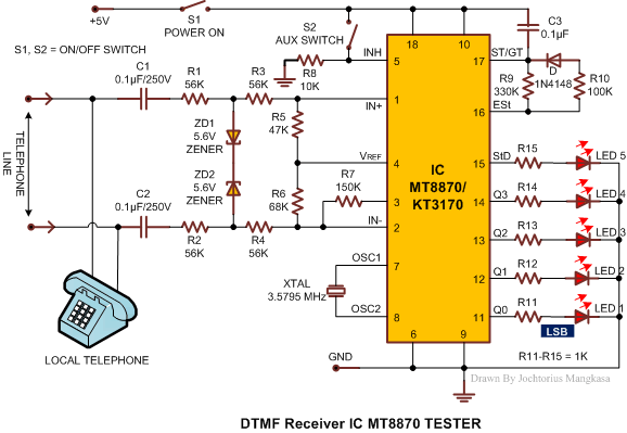 Today, most telephone equipment use a DTMF receiver IC. One common DTMF receiver IC is the Motorola MT8870 that is widely used in electronic communications circuits. The MT8870 isan 18-pin IC. It is used in telephones and a variety of other applications. When a proper output is not obtained in projects using this IC, engineers or technicians need to test this IC separately. A quick testing of this IC could save a lot of time in research labs and manufacturing industries of communication instruments. Here’s a small and handy tester circuit for the DTMF IC. It can be assembled on a multipurpose PCB with an 18-pin IC base. One can also test the IC on a simple breadboard. For optimum working of telephone equipment, the DTMF receiver must be designed to recognize a valid tone pair greater than 40 ms in duration and to accept successive digit tone-pairs that are greater than 40 ms apart.
Posted on Monday, October 11, 2010 • Category: Phone Circuits
 Here is a telephone remote circuit which enables switching ‘on’ and ‘off’ of appliances through telephone lines. It can be used to switch appliances from any distance, overcoming the limited range of infrared and radio remote controls.
Posted on Saturday, October 9, 2010 • Category: Phone Circuits
 An interesting circuit for a me- dium performance handy electronic telephone receiver, suited for receiving incoming calls, is described here. This circuit can be connected to almost all types of telephone exchange lines. To simplify the gadget, the dialler section has been omitted. The circuit can be constructed on a medium size veroboard. Wiring and components layout are not very critical. For compactness, enclose the wired circuit in a plastic cabinet as shown in Fig.(a) here. In order to prevent undesired acoustic feedback, it is necessary to adjust the orientation of ear-piece (LS) and mouth-piece (MIC) at the final stage of construction. The circuit consists of four sections: ringer, voltage regulator, transmitter and receiver. The ringer section is built around capacitor C1, resistor R1 and electronic buzzer BZ1.
Posted on Thursday, April 10, 2008 • Category: Phone Circuits
 It might be "yet another" «device» controller that operates over phone-line, but this one works for sure :) The task was to build a device that connects to the phone line and has a relay as an output switch. It should also sense if the connected «consumer» is turned-on or off and report to the administrator at the other end of the phone line. The administrator would then call-in the device, log in with the password, and check the state of «consumer», turn it on or off, change password or some other settings. Current version has only one relay.
Posted on Wednesday, April 9, 2008 • Category: Phone Circuits
Just hook this Alarm Phone Dialer up to something you would like to monitor, for example, a high water alarm, low temperature alarm, back window, garage door, etc. When the system is activated it will call a number of programmed numbers to let you know the alarm has been activated. This would be great to get alerts of alarm conditions from your home when you are at work. The microcontroller code is provided on the site.
Circuit-Zone.com © 2007-2026. All Rights Reserved.
|